
Machine family01
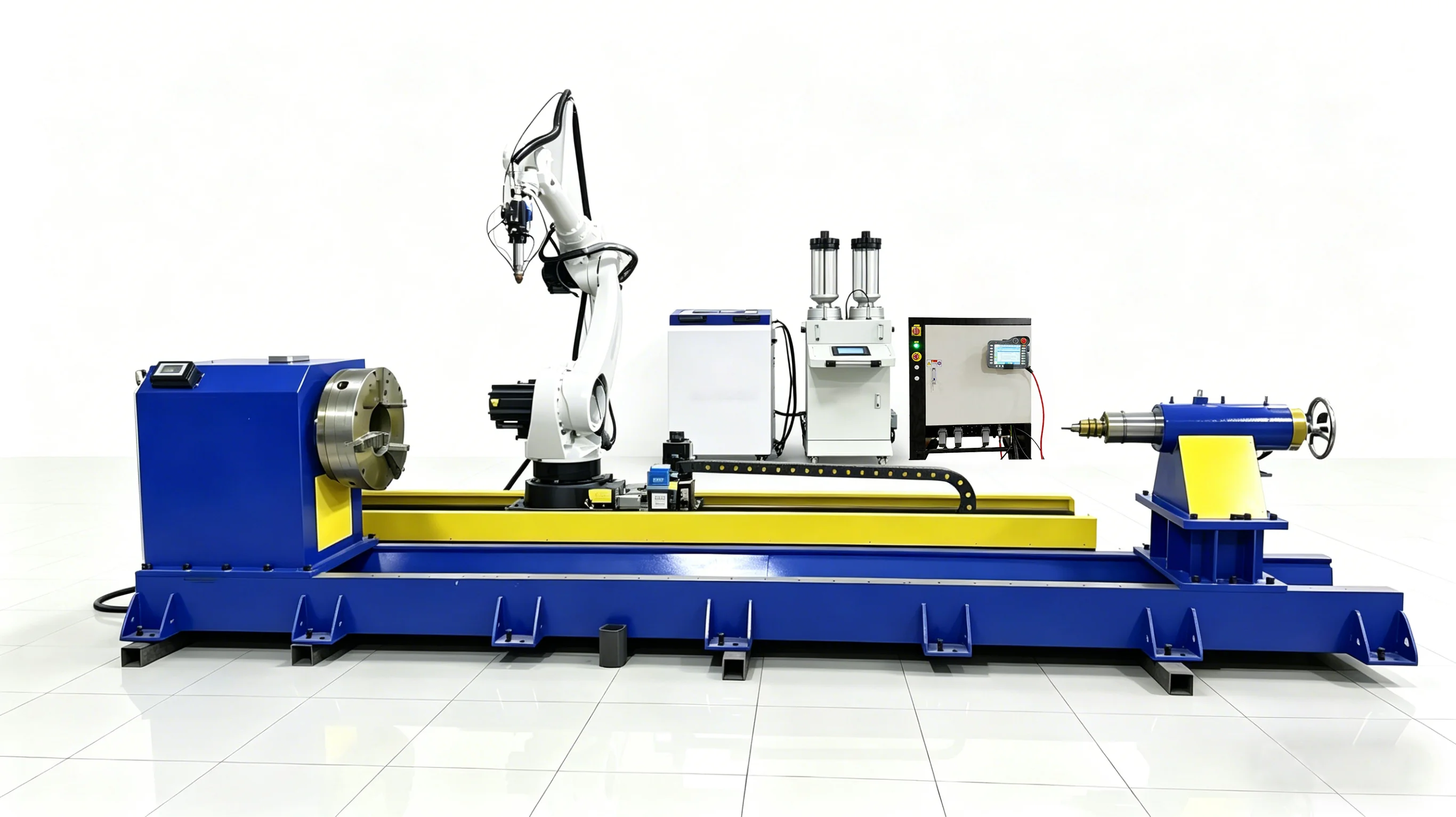
Internal-wall laser cladding machine
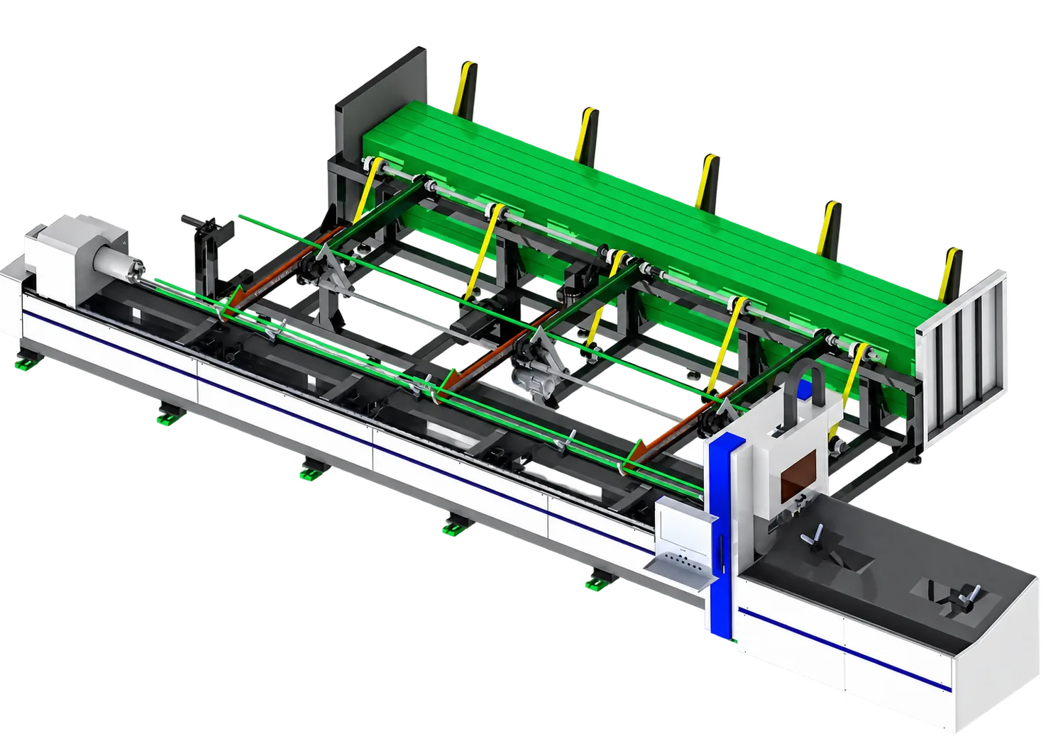
Internal-wall cladding configuration for pipes, cylinders, sleeves and other rotational parts.
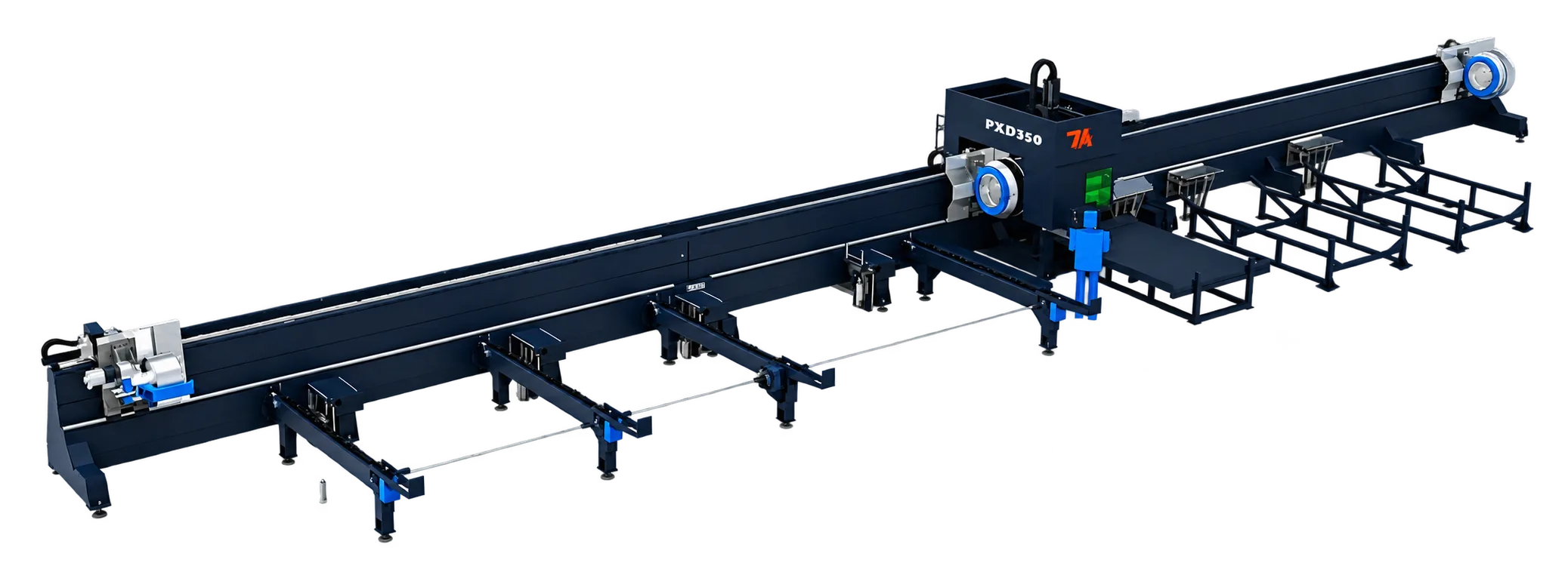
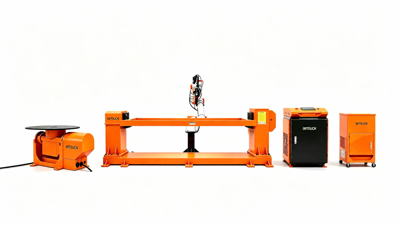
View details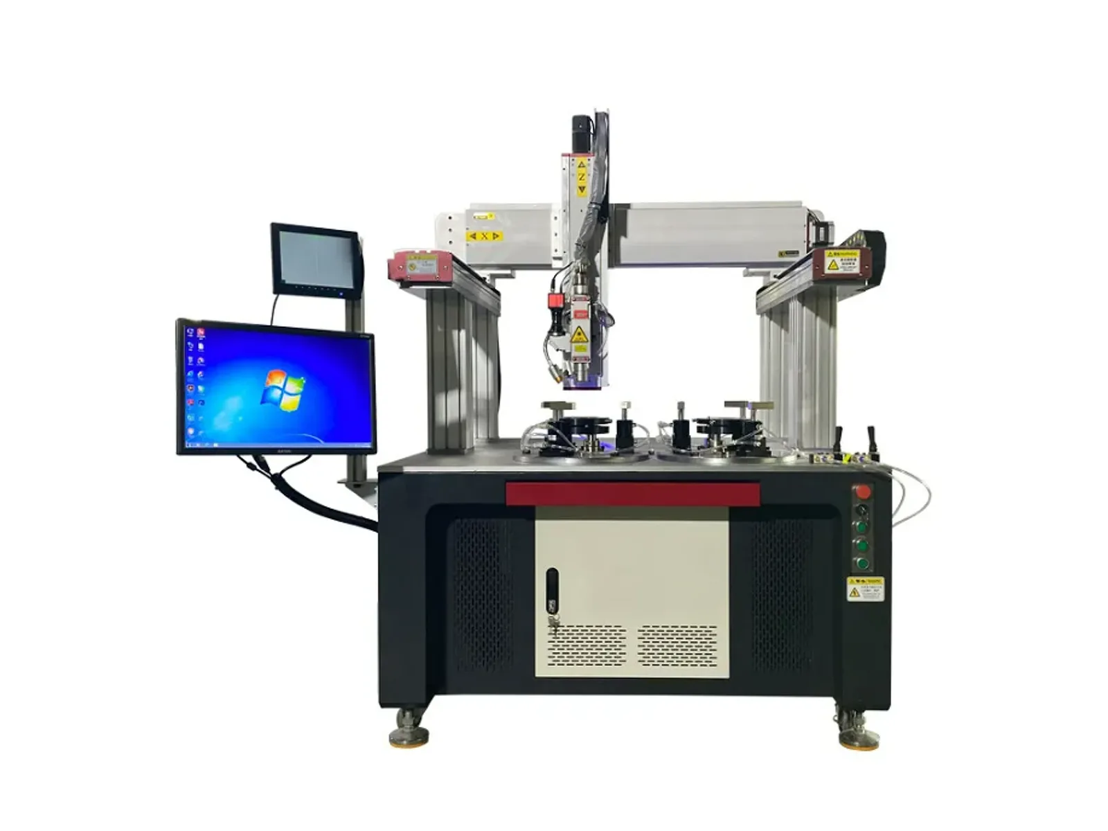 Gantry automatic laser welding machineServo multi-axis gantry system with CCD positioning, 1.5-6 kW configurations and a custom working stroke for the submitted workpiece.
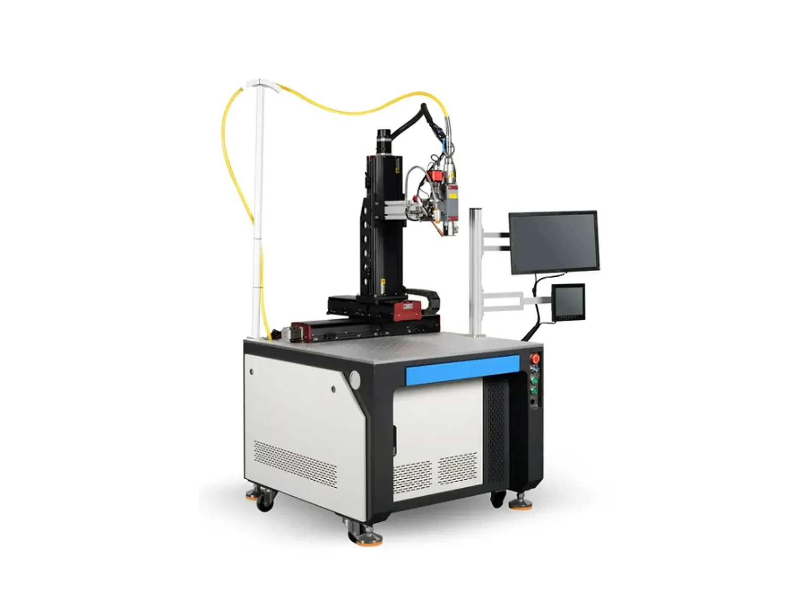 Four-axis automatic laser welding machineFour-axis linkage with CCD-assisted positioning, 1-6 kW configurations and ±0.02 mm repeat positioning for curved and special-shaped weld paths.
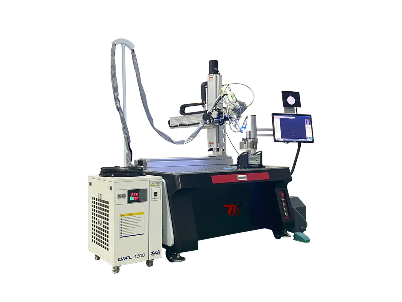 Five-axis automatic laser welding machineFive-axis servo linkage with CCD positioning, 1-6 kW configurations and ±0.02 mm repeat positioning for three-dimensional curved and special-shaped seams.
Select laser cladding equipment for a component-repair process, from shafts and internal bores to screw flights and large working surfaces. Start with the damage, base material and access, then define deposition, finishing and inspection requirements.
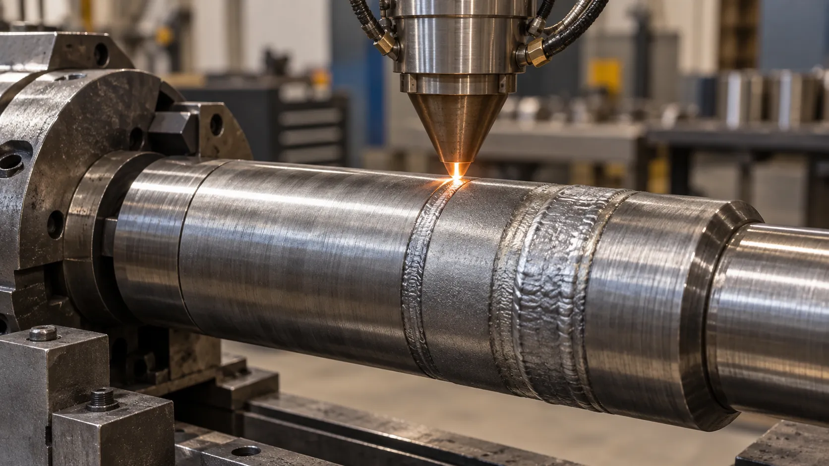
This page supports equipment selection and integration for repair applications. Review the original component, its worn condition and the required final surface to determine whether cladding is suitable and which machine can reach the area. The application examples describe process requirements, not an offer of an on-site repair crew or a guarantee that every damaged part can be restored.

Map worn, scored or corroded areas on piston rods, screws and bearing surfaces. Provide original and remaining dimensions, overall part length and diameter, and the support or rotation arrangement to be reviewed.
Define the deposited layer and finishing allowance needed for the target dimension, then confirm the equipment and inspection scope.
For cylinders, pipelines, barrels or similar internal surfaces, specify bore diameter, depth, access opening and the position of damage. Review head clearance and process access over the complete area.
Confirm the chosen internal-wall configuration against the actual geometry and any sealing-surface requirements.
Identify worn screw flights, screw heads or check-ring surfaces from injection-molding or extrusion equipment. Include profile dimensions, access between features and operating conditions when reviewing the deposition path.
Agree the target surface, material selection and finishing requirements instead of assuming one configuration reaches every screw profile.
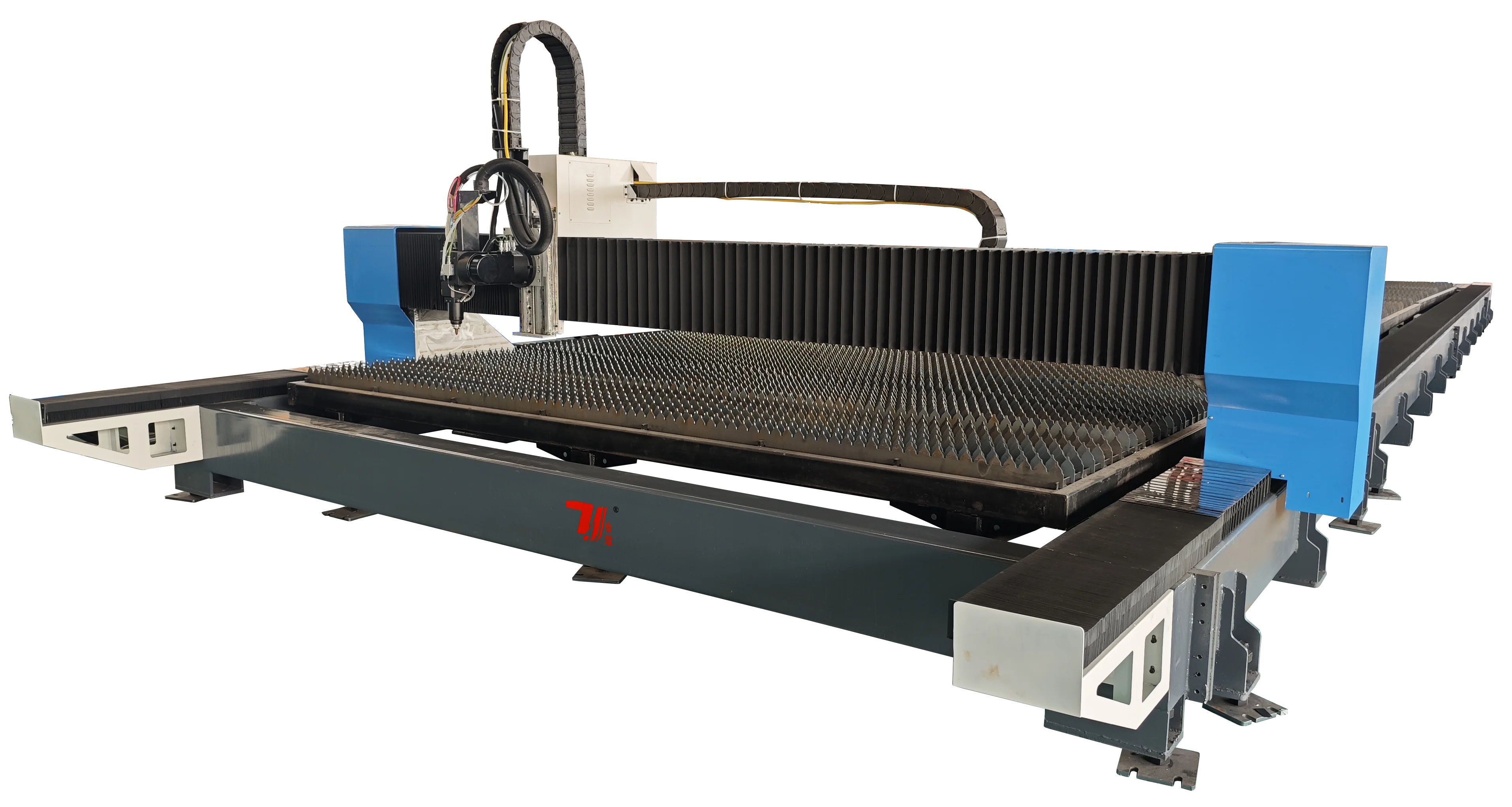
Submit models and handling constraints for large platens, molds, valves, brake discs or other complex surfaces. Review motion, workholding and any proposed machining interface as part of the equipment project.
Gantry, robot or combined-process concepts require a confirmed package; downstream turning or finishing is not automatically included.
Explore equipment for the processes above. Fixture and automation choices depend on your part geometry and production requirements.
Internal-wall cladding configuration for pipes, cylinders, sleeves and other rotational parts.
View details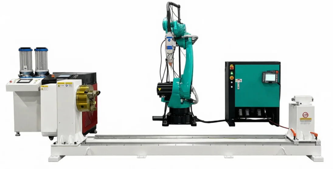
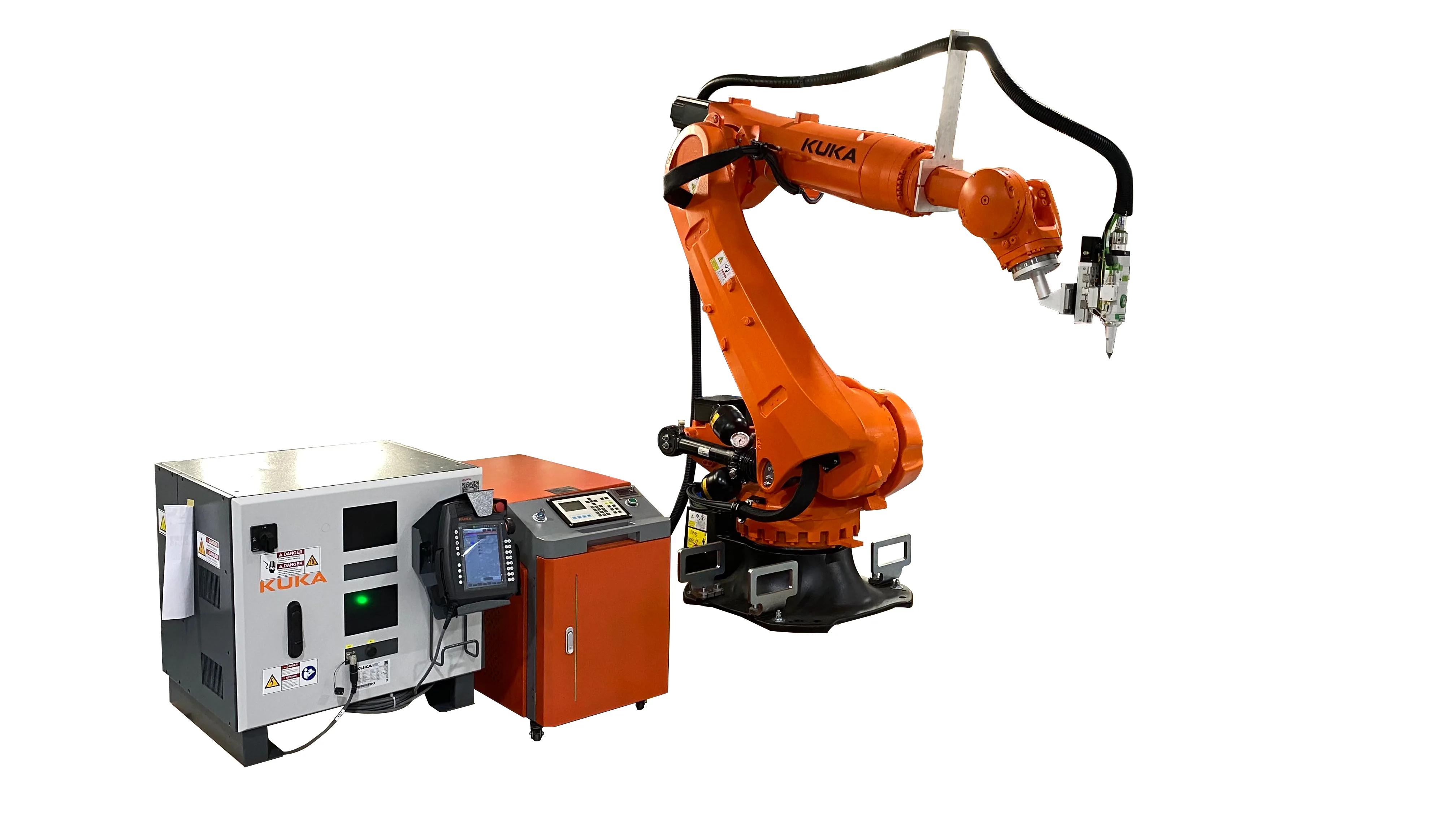
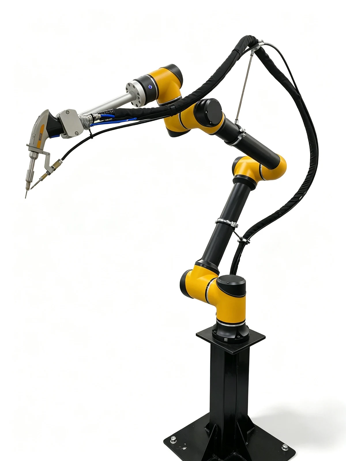
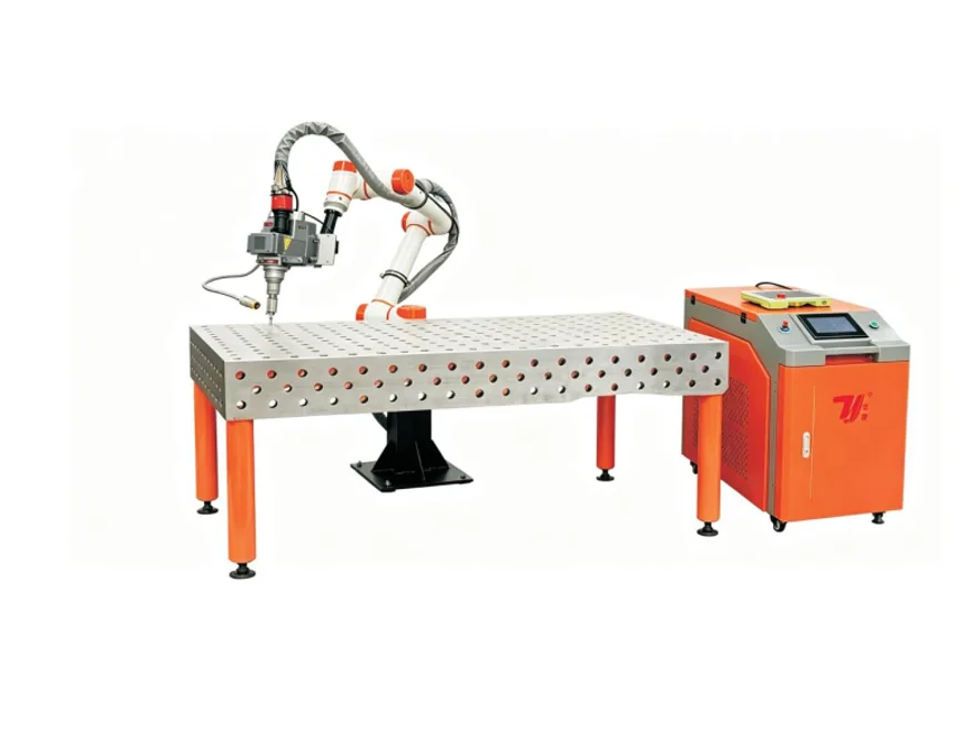
Robot-integrated workstation for cladding repair and surface-strengthening configurations.
View details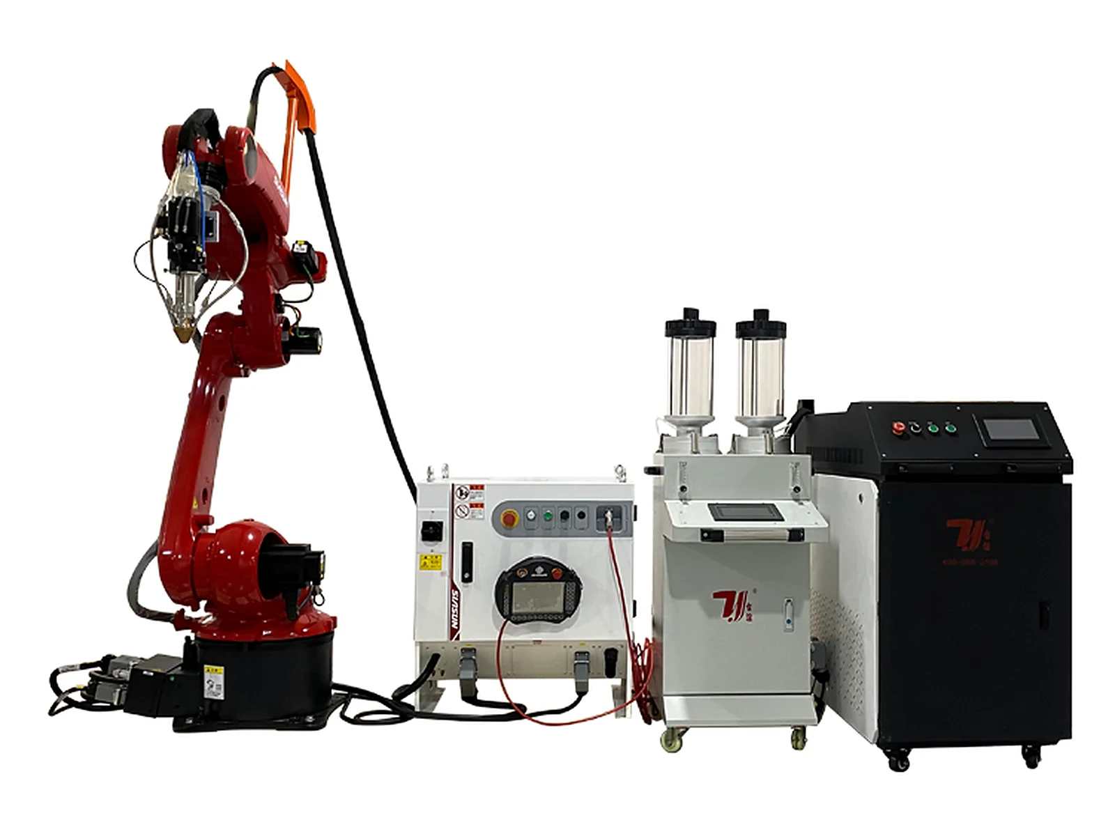
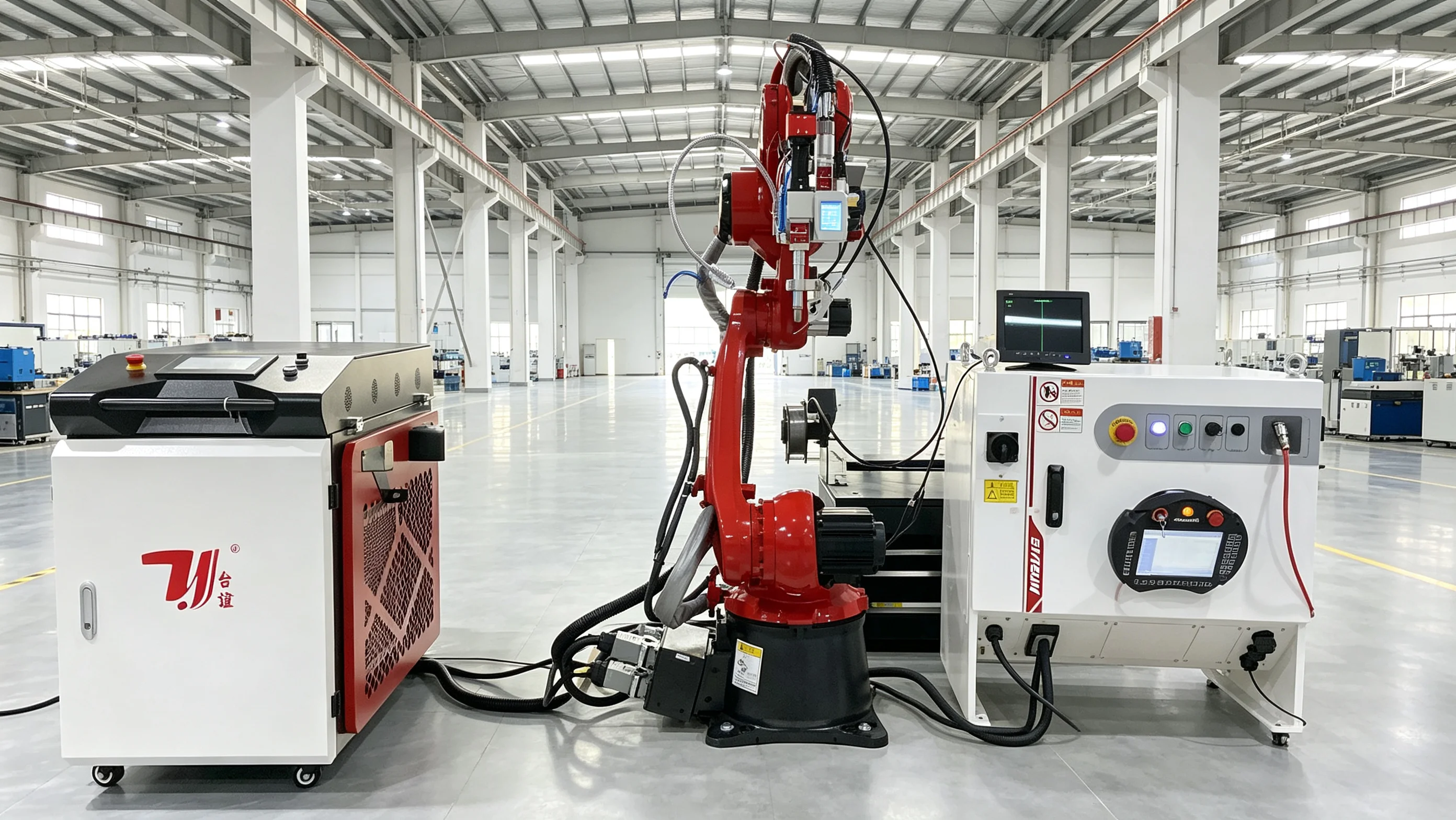
Robot cladding configuration for flat, axial, curved and special-shape workpieces.
View detailsDedicated shaft systems for worn, scored or corroded surfaces on rods and bearing areas.
Internal-bore systems for worn or corroded cylinder, pipeline and barrel surfaces.
Dedicated screw systems for worn flights, screw heads and check rings used in plastics processing.
Gantry and robotic configurations for complex surfaces, plus combined cladding and turning lines for brake discs.
This page is for selecting and configuring equipment for component-repair processes. It does not establish an on-site repair service, collection arrangement or repair turnaround commitment.
Shaft and rod surfaces, internal bores, screw flights and large or complex parts create different reach, support and motion requirements. Provide the full geometry and damaged area to review a suitable configuration.
Send drawings, base material, original and worn dimensions, photographs and damage location. Include part weight, access constraints, operating conditions and the required final dimensions and surface condition.
The deposited layer and final finished surface are separate requirements. Confirm allowances, any subsequent machining or finishing, inspection and responsibility for those steps in the project scope.
Review the base material, damage, proposed deposition material and required service conditions. Define trials or inspection needed for acceptance; the application list does not guarantee that every worn or cracked component is repairable.
Request a quote
Describe your component, base material, dimensions and operating conditions. Include the worn or corroded area, bore or surface access, and the repair or strengthening requirements.