
Machine family01
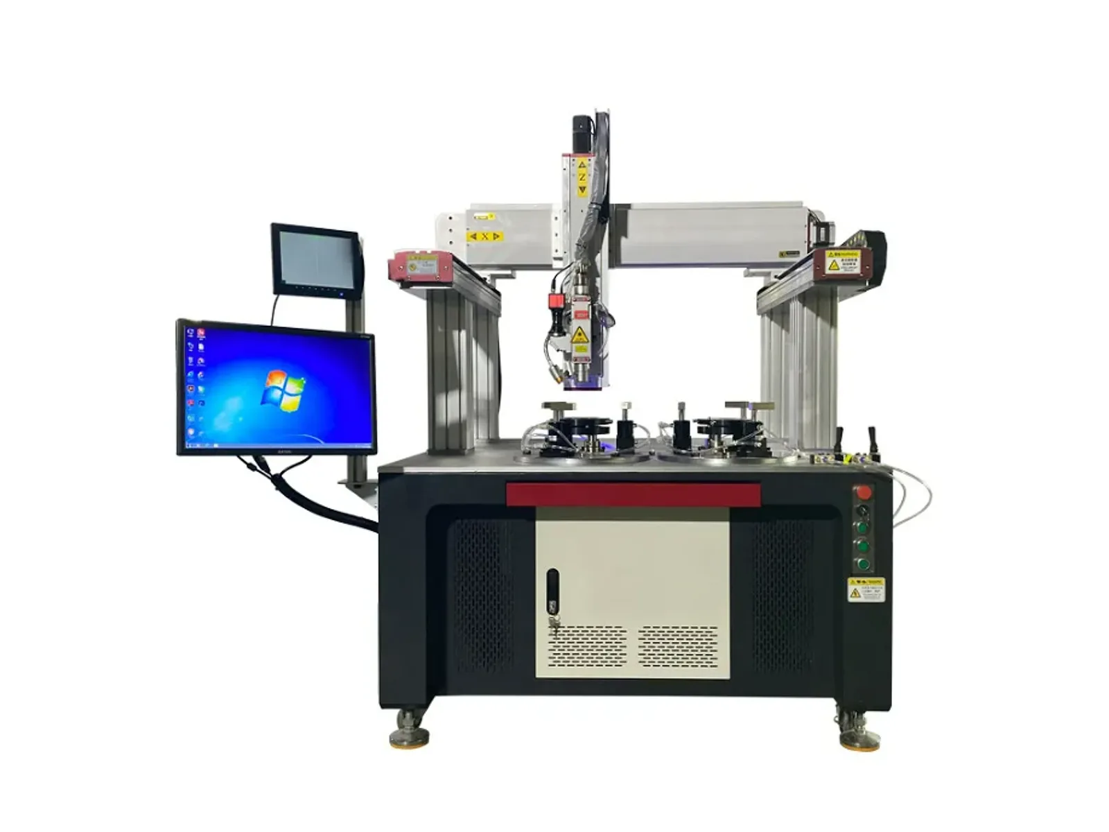
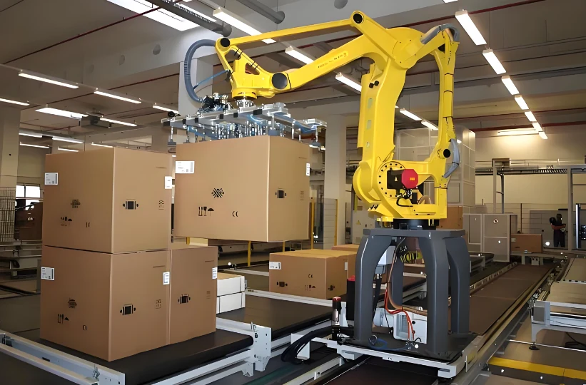
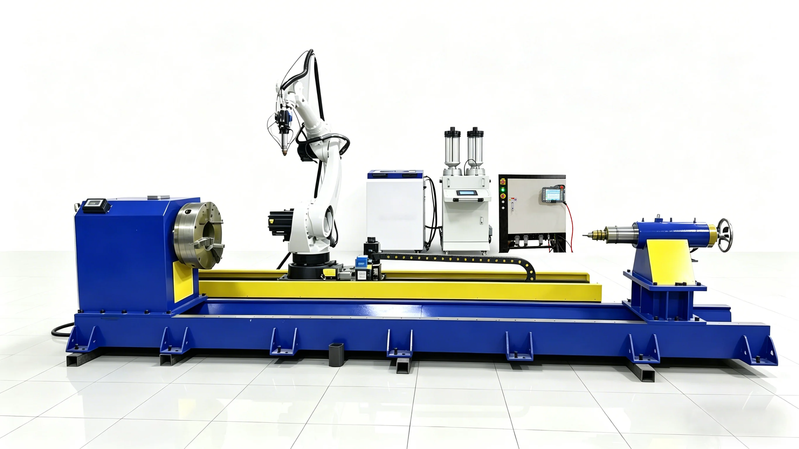
Gantry automatic laser welding machine
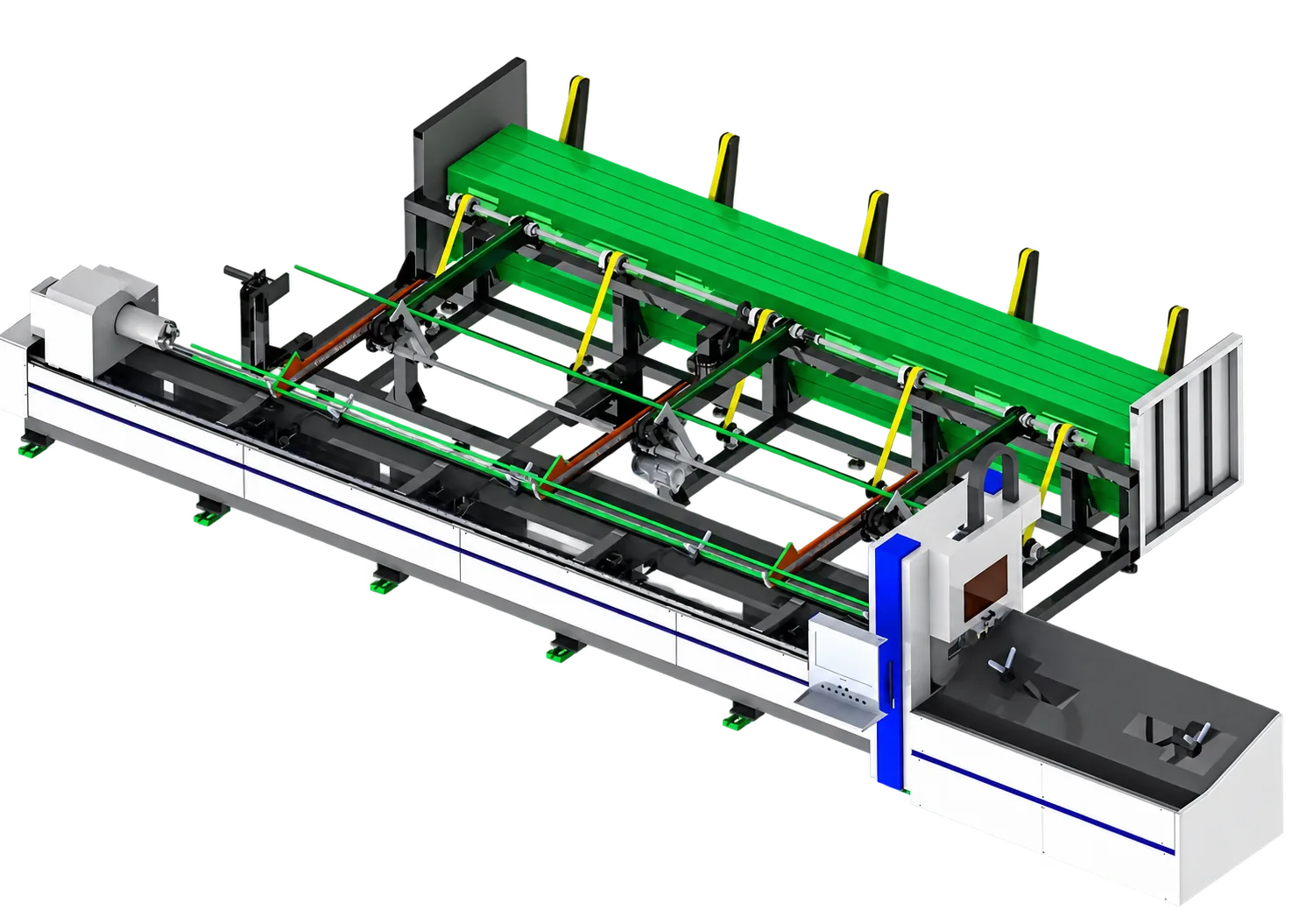
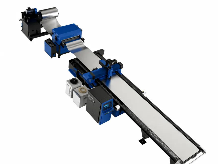
Servo multi-axis gantry system with CCD positioning, 1.5-6 kW configurations and a custom working stroke for the submitted workpiece.
View details →
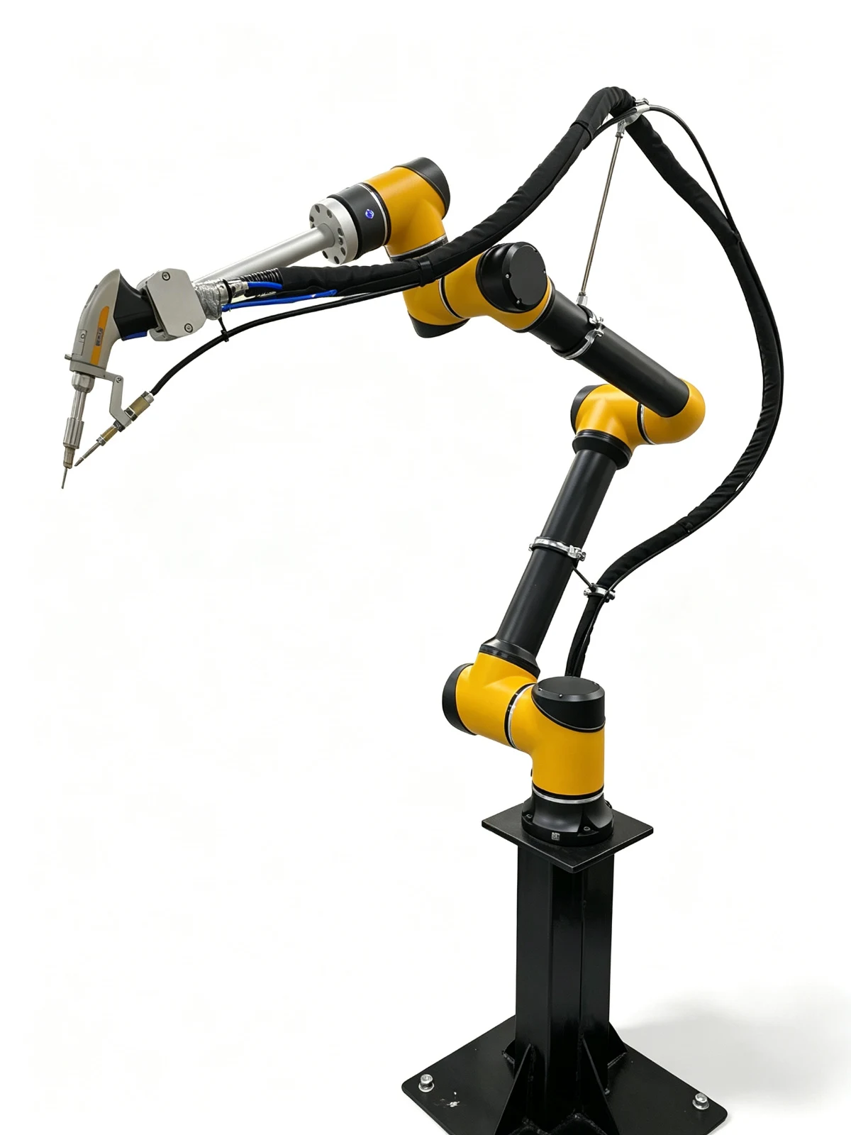
Gantry automatic laser welding machineServo multi-axis gantry system with CCD positioning, 1.5-6 kW configurations and a custom working stroke for the submitted workpiece.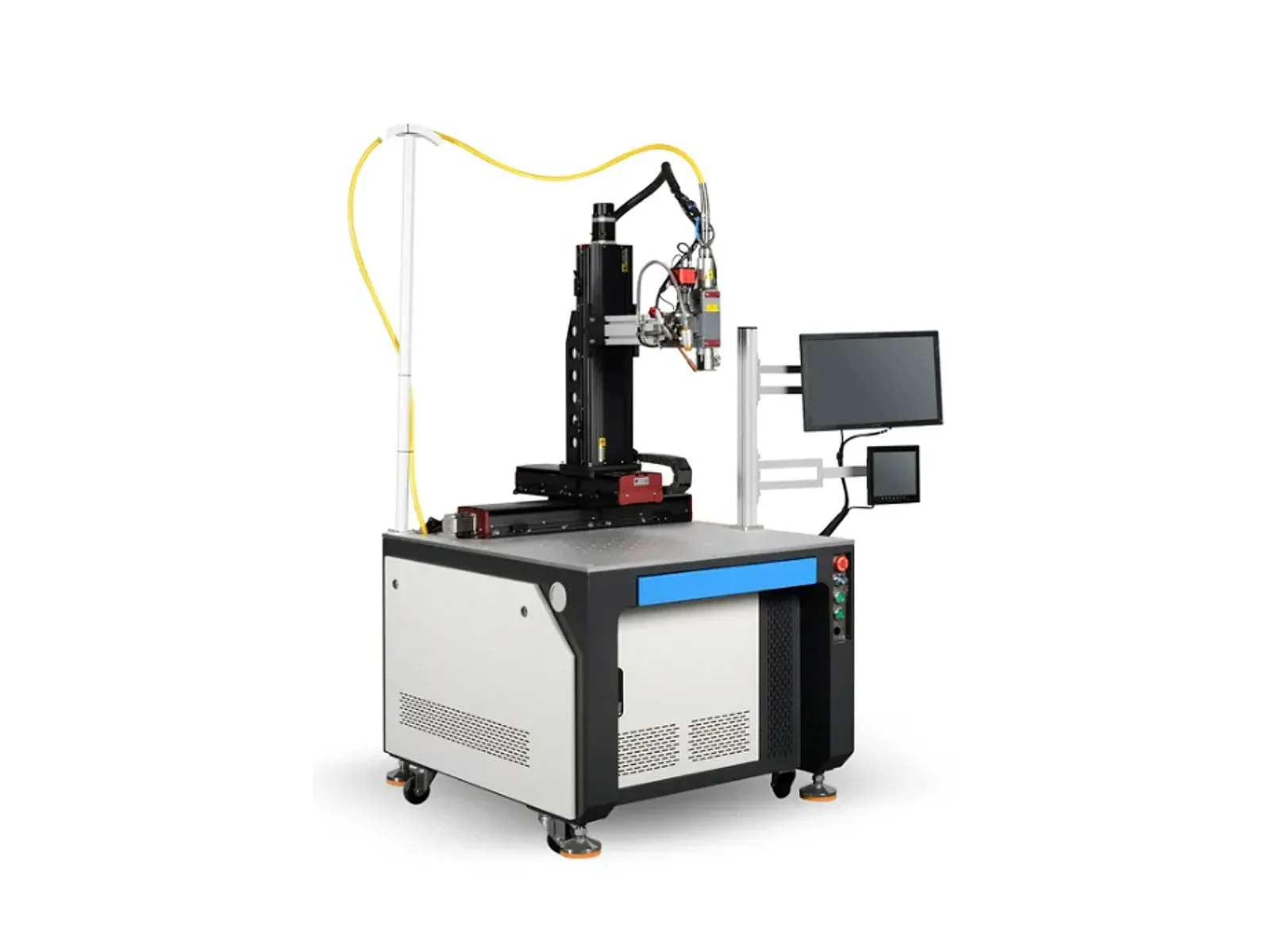 Four-axis automatic laser welding machineFour-axis linkage with CCD-assisted positioning, 1-6 kW configurations and ±0.02 mm repeat positioning for curved and special-shaped weld paths.
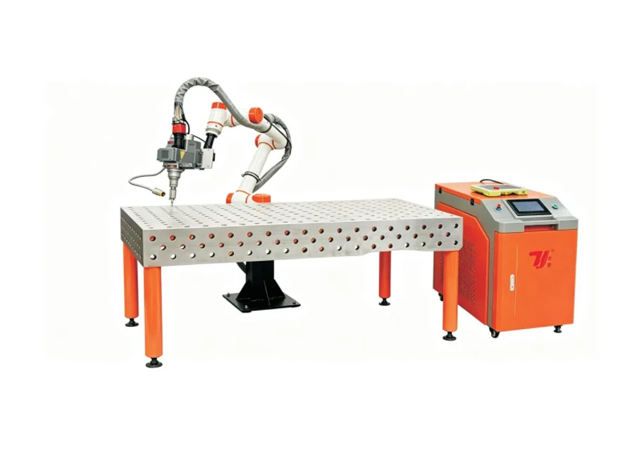
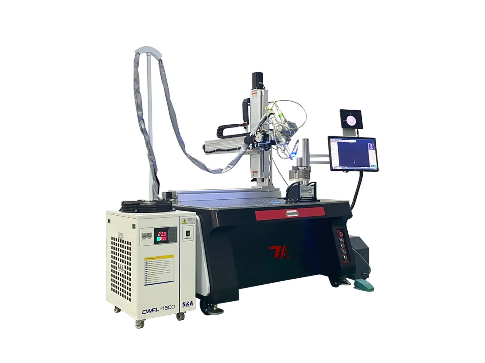 Five-axis automatic laser welding machineFive-axis servo linkage with CCD positioning, 1-6 kW configurations and ±0.02 mm repeat positioning for three-dimensional curved and special-shaped seams.
Automatic welding
Compare gantry, four-axis, five-axis and dedicated welding stations for your workpiece. Choose the motion, fixture and loading workflow around the weld seam.
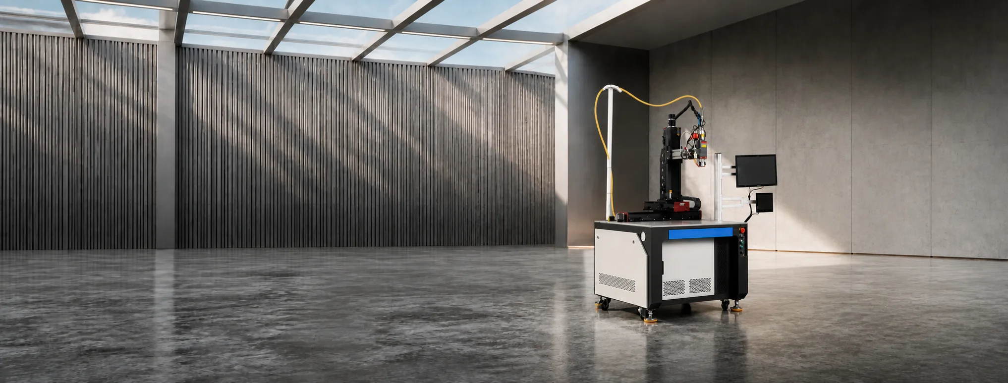
Servo multi-axis gantry system with CCD positioning, 1.5-6 kW configurations and a custom working stroke for the submitted workpiece.
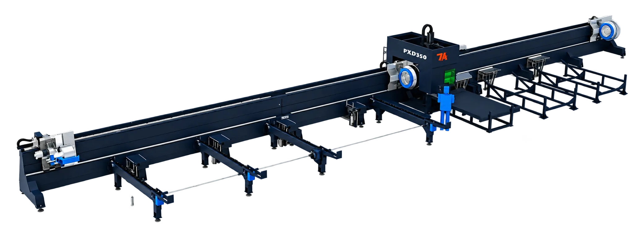
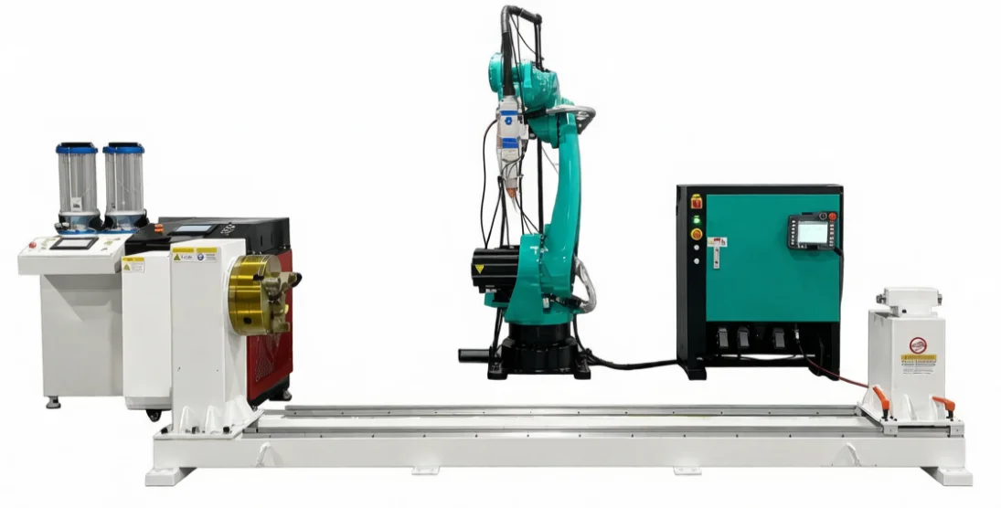
Four-axis linkage with CCD-assisted positioning, 1-6 kW configurations and ±0.02 mm repeat positioning for curved and special-shaped weld paths.
Five-axis servo linkage with CCD positioning, 1-6 kW configurations and ±0.02 mm repeat positioning for three-dimensional curved and special-shaped seams.
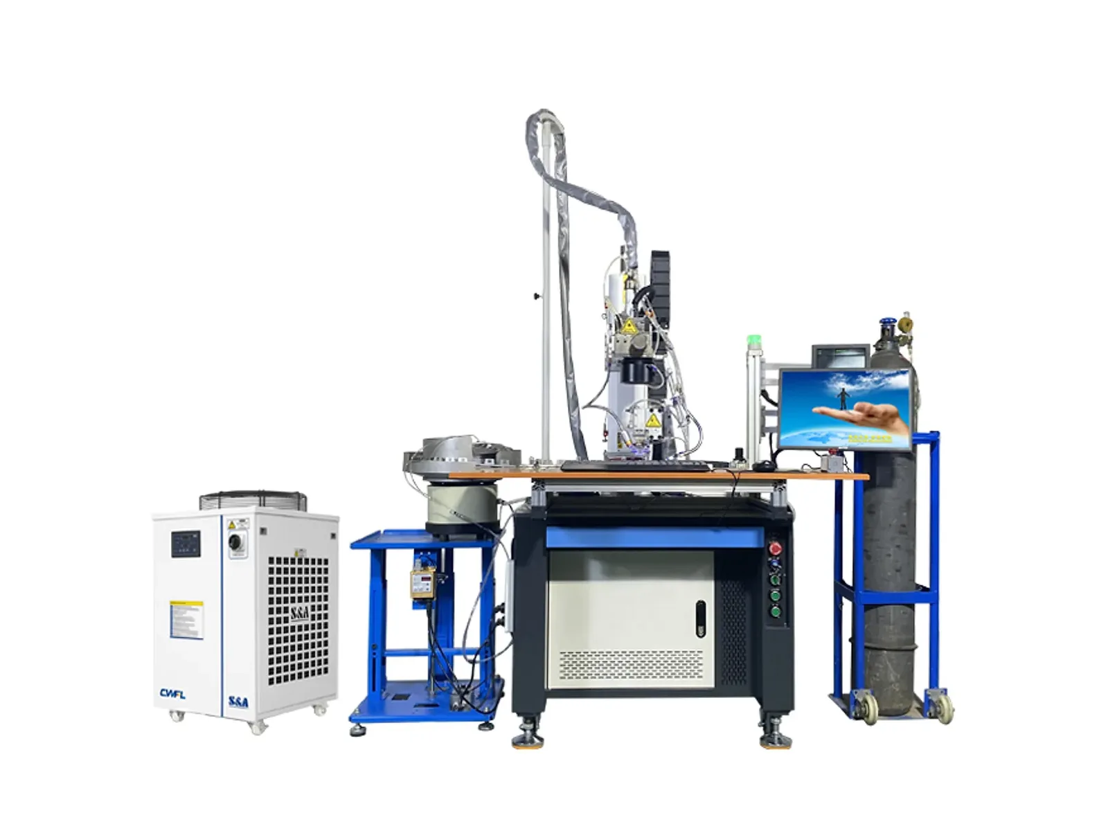
Dedicated fixture-based system with 1.5-6 kW power, 8-80 mm/s welding speed and ±0.02 mm positioning for stainless-steel sink clamps and accessories.
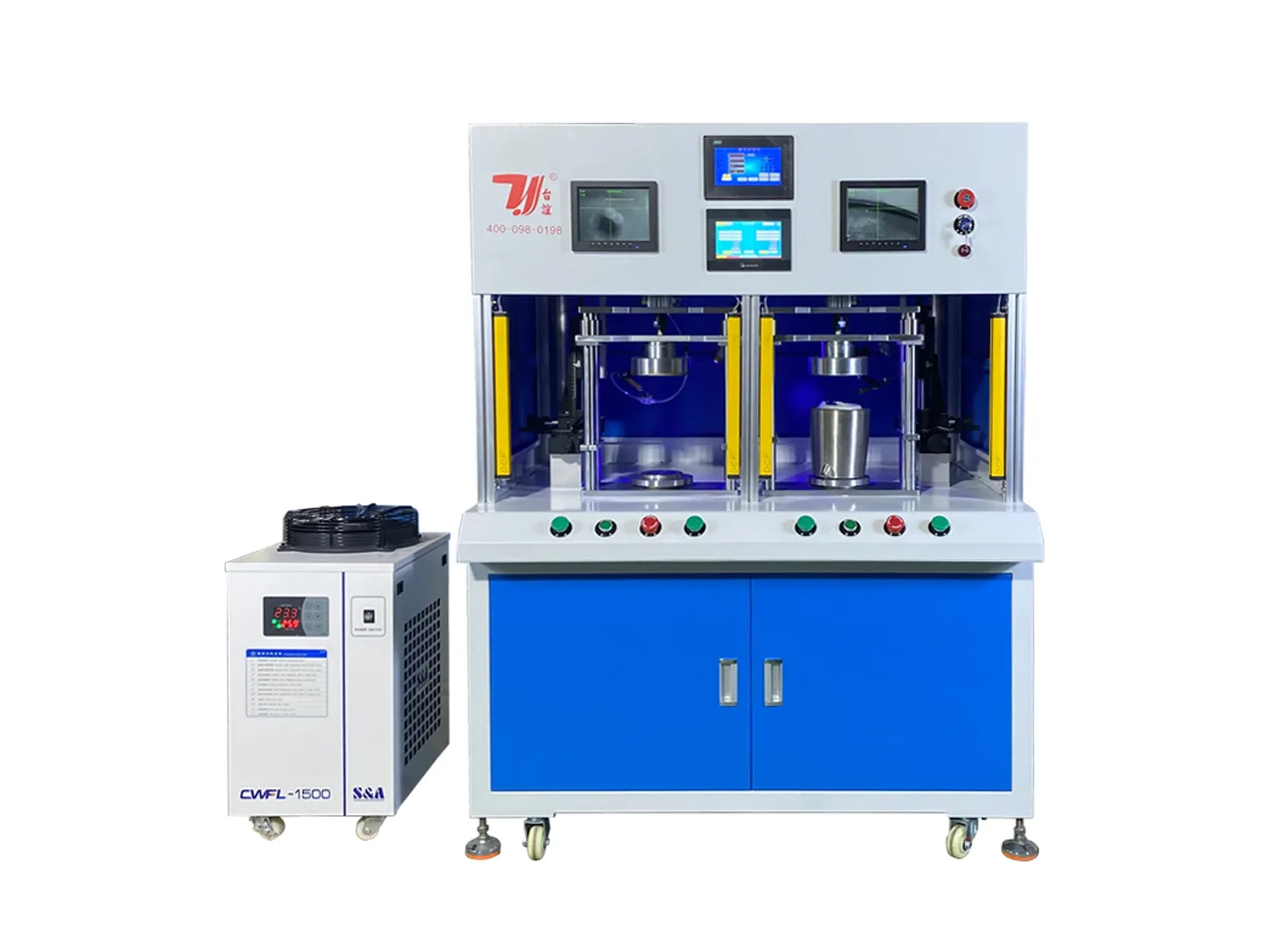
Alternating dual-station system with 1.5-6 kW power, 10-90 mm/s welding speed and ±0.02 mm positioning for kettle and vessel bottoms.
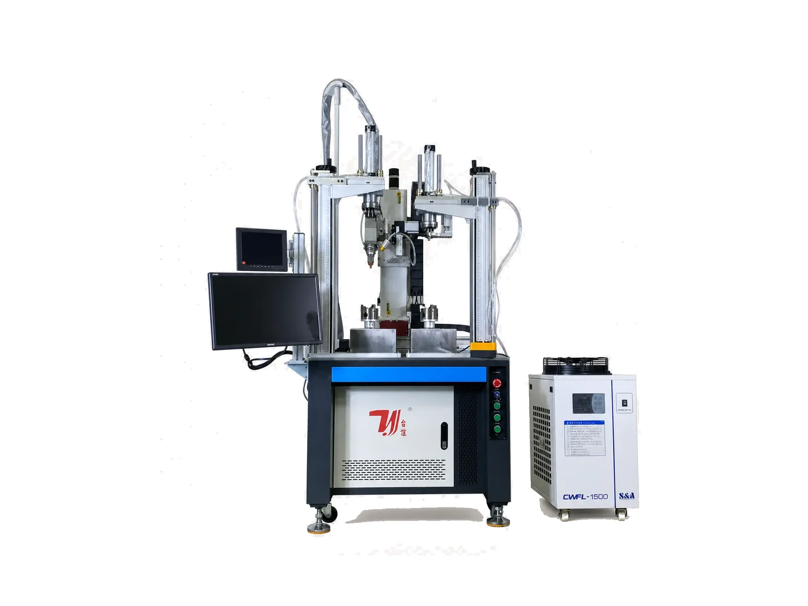
Dual-station fixture-guided system with 1.5-6 kW options, CCD-assisted operation and ±0.01 mm repeat precision for faucet bodies and intersecting pipe seams.
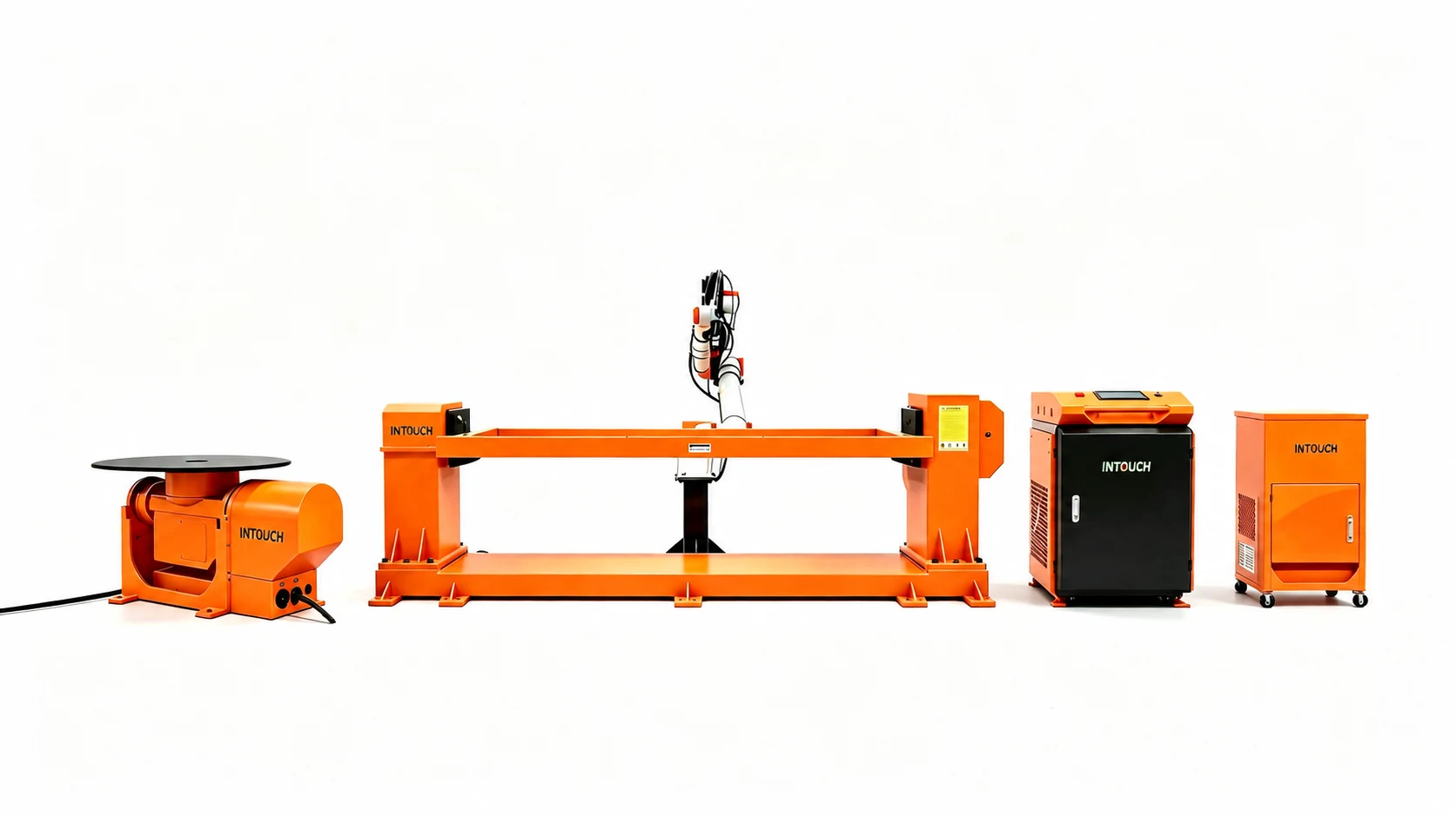
Background-cleaned equipment visualization; final fixture package is project-specific.
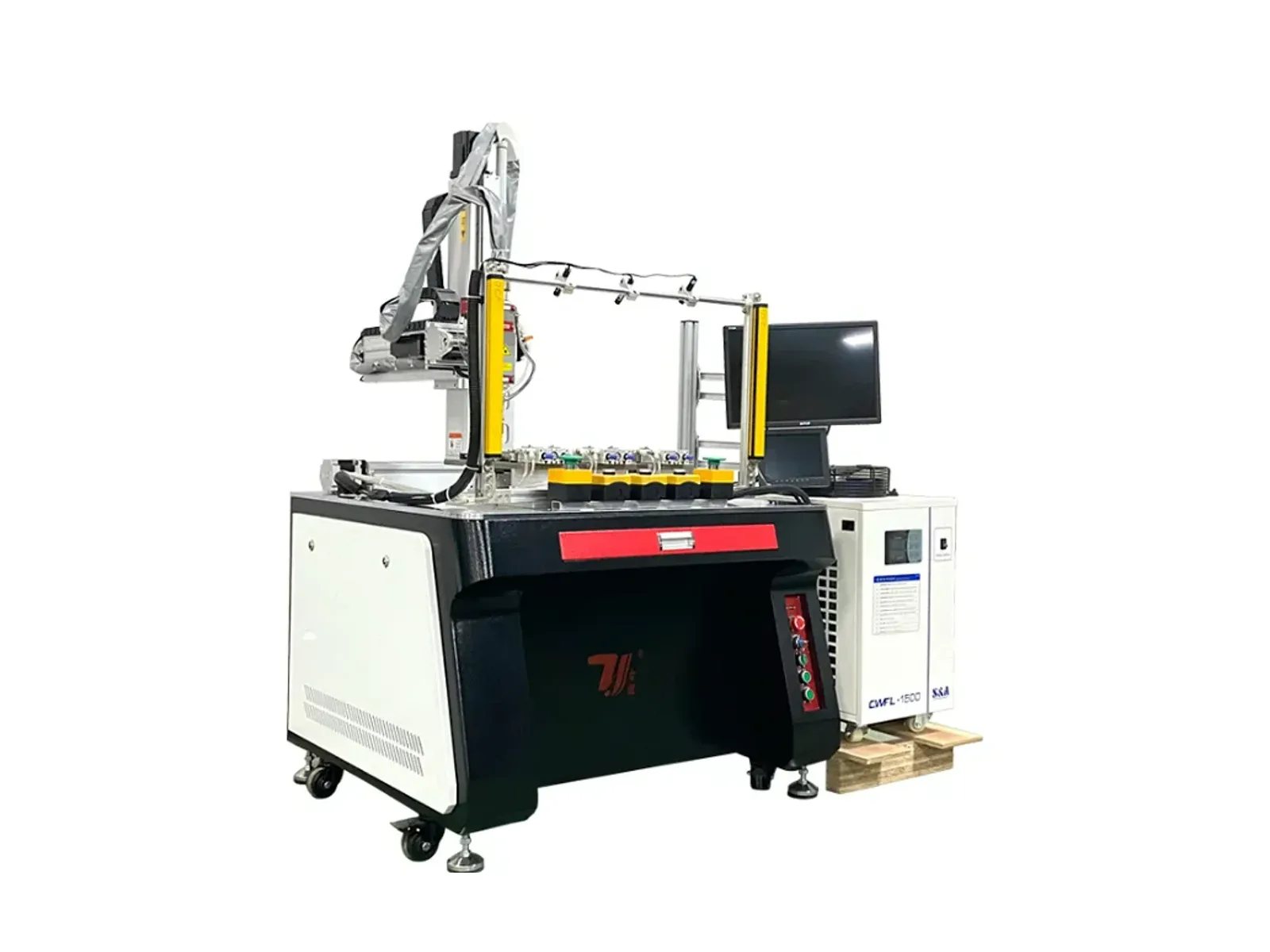
Rotary multi-station system with 1.5-6 kW options, 8-90 mm/s listed speed and custom fixtures for repeat stainless-steel kettle-spout joints.
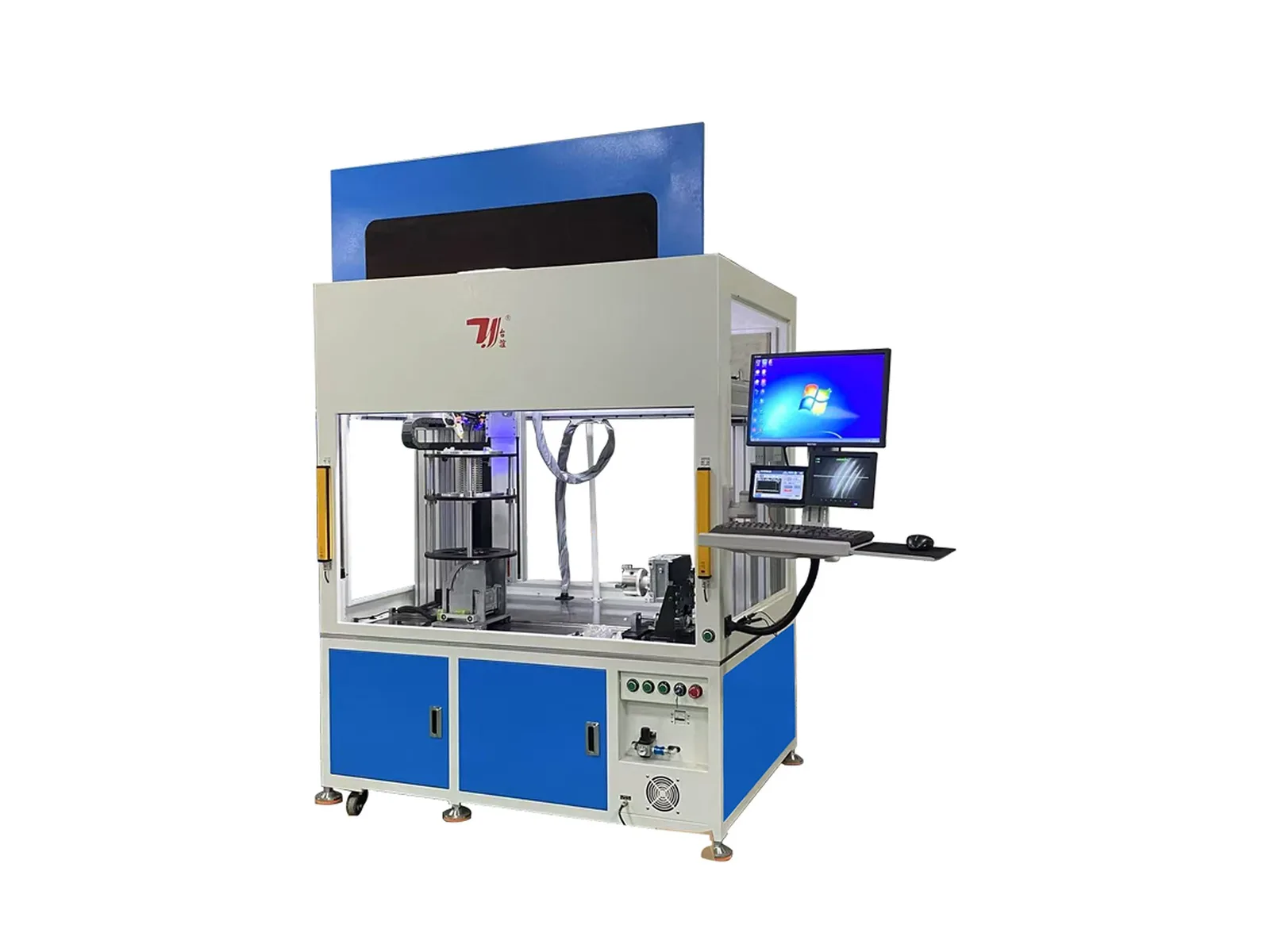
Rotary-fixture welding system with CCD tracking, 1-3 kW power, 5-80 mm/s speed and ±0.02 mm positioning for bellows, metal hoses and compensator joints.
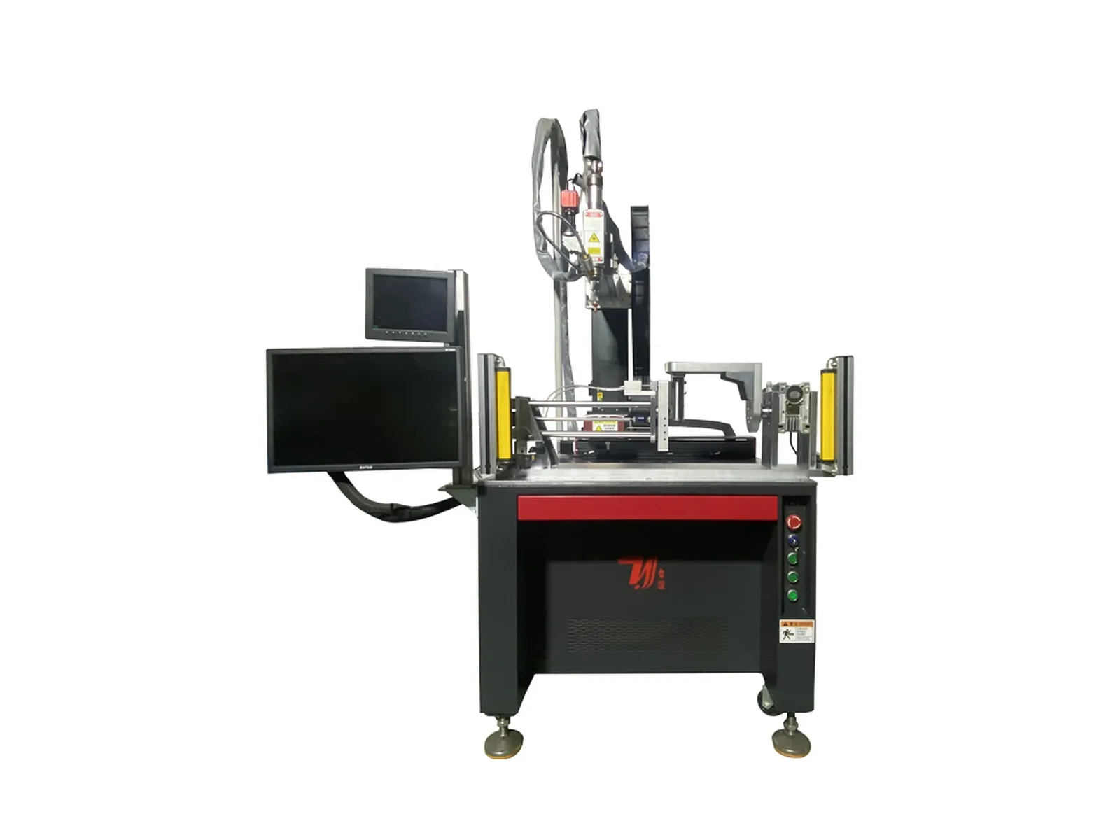
Dedicated rotary-fixture system with CCD support, 1.5-6 kW listed options, 8-90 mm/s speed and ±0.02 mm positioning for kettle and coffee-pot spout joints.
Compare the weld path, access to the joint and how the part will be held before choosing an automatic laser welding machine. Gantry and multi-axis systems address different motion requirements; dedicated stations organize the process around a particular workpiece. Include loading and unloading in the comparison, because automatic welding does not necessarily mean automatic part handling.
Review the gantry system when working stroke and access across the workpiece are central to the project. Submit the part dimensions and seam drawing so the motion range and fixture can be specified together.
Compare the four-axis system for the listed curved and special-shaped weld paths. Check how the fixture positions the joint and which movements are needed; an axis count alone does not establish compatibility with a part.
Review the five-axis configuration for three-dimensional curved and special-shaped seams. Define the joint orientation and access requirements before selecting the motion and workholding arrangement.
The range includes sink-clamp, kettle-bottom, tee-pipe, spout and bellows systems. For example, the double-station kettle-bottom machine uses alternating work positions. Compare the station sequence against the actual component and loading task.
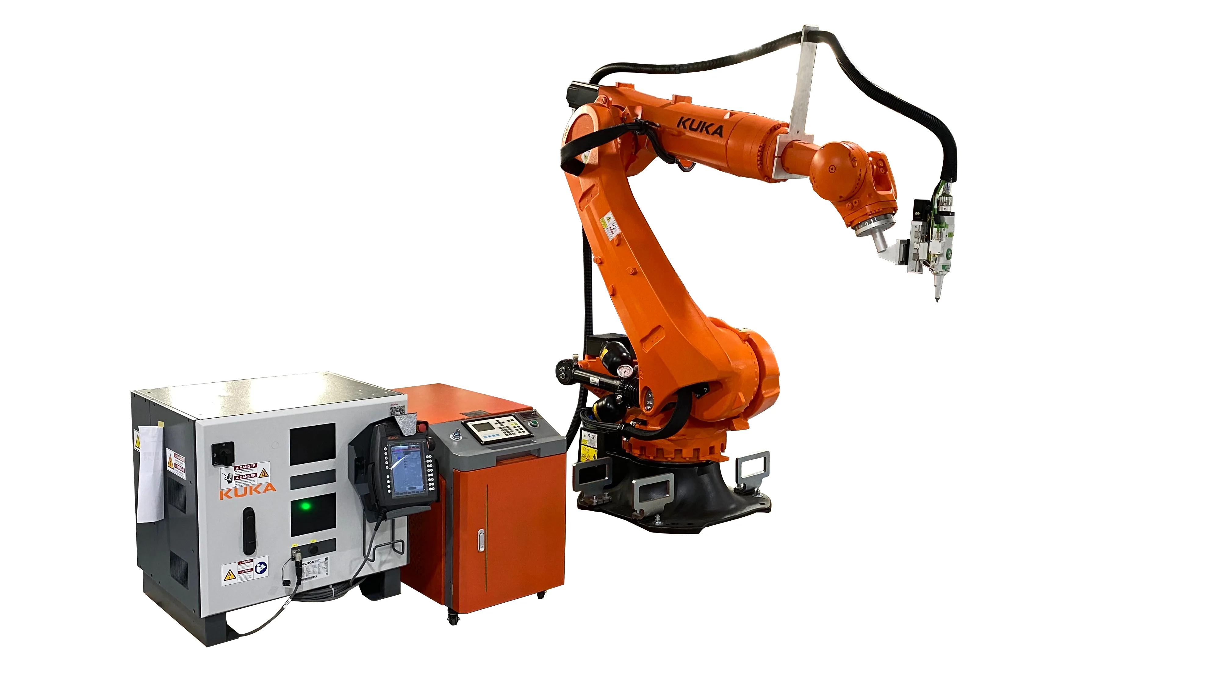
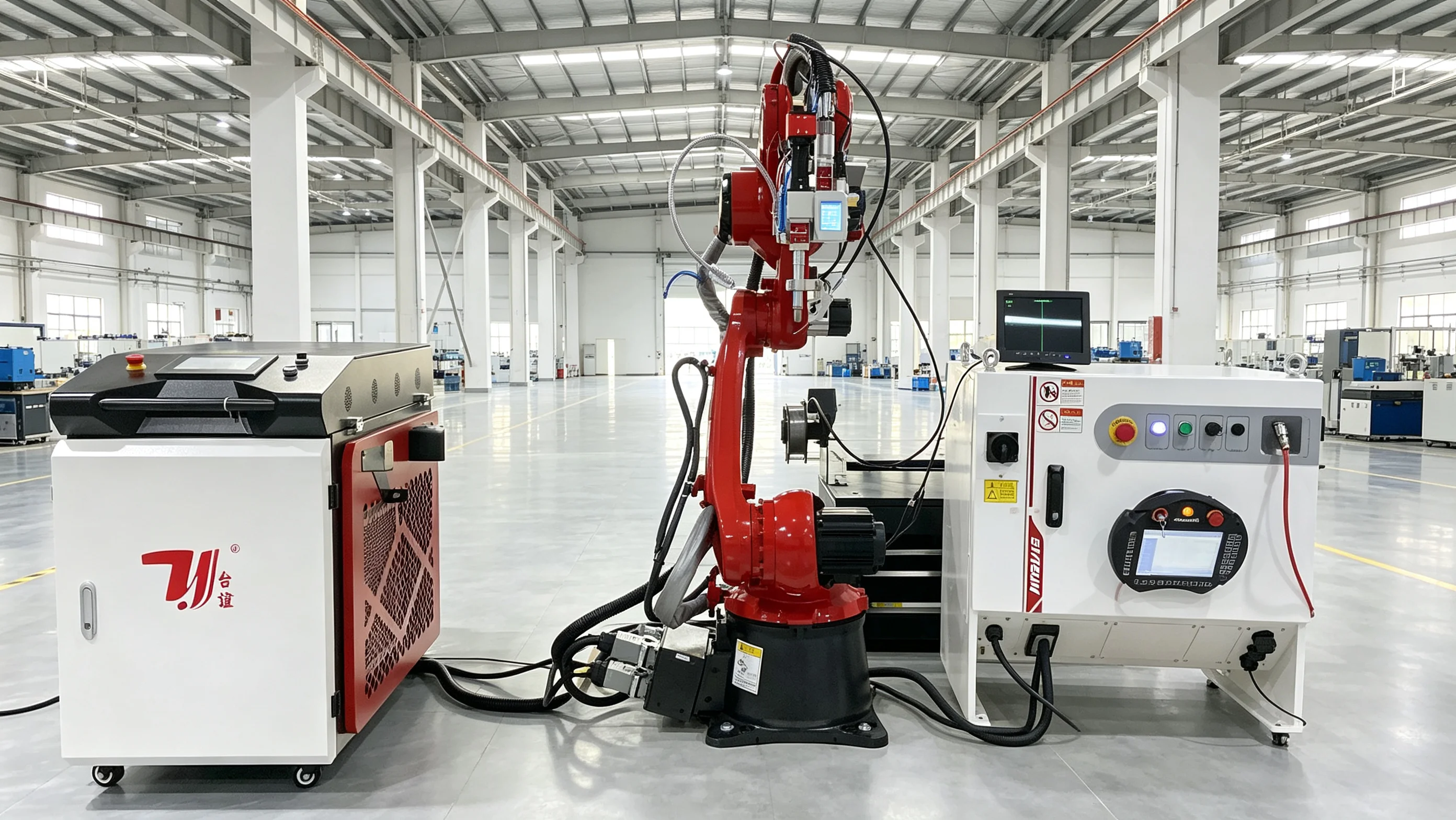
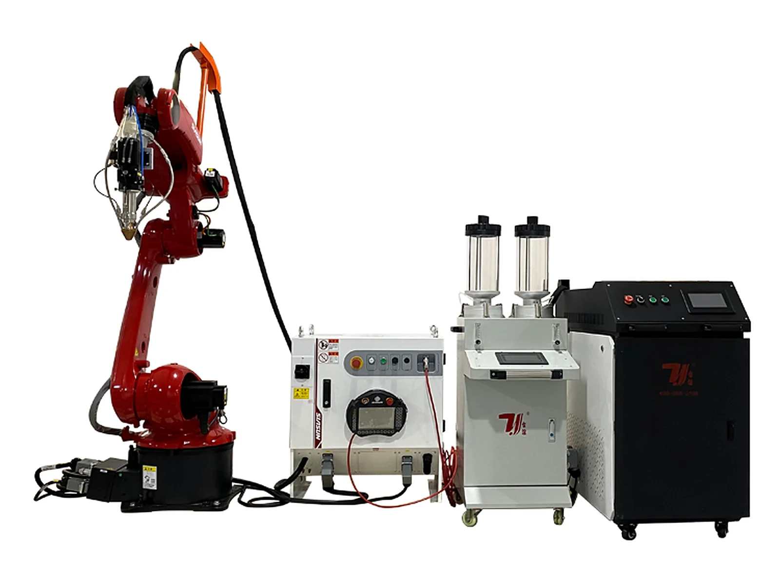
If the project calls for a robot-mounted welding head, compare the separate robot systems range. Its cell layout and fixture requirements should be evaluated against the same part drawing and acceptance criteria.
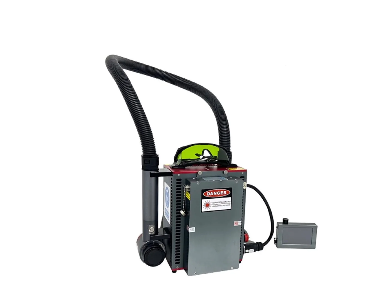
In this range, the machine controls the welding motion through a gantry, multi-axis mechanism or dedicated fixture arrangement. The equipment and operator tasks differ by model. Confirm how parts are loaded, clamped, welded and removed rather than assuming the complete cycle is unattended.
Start with the seam geometry and the orientation needed to reach each joint. Compare the motion and fixture arrangement with the drawing. Additional axes may address a positioning requirement, but do not by themselves guarantee a better weld or a shorter cycle for every part.
Consider a dedicated station when the workpiece matches a listed application, such as sink clamps, kettle bottoms, spouts, tee pipes or bellows. Review the part variations, fixture change requirements and loading sequence before choosing it over a general motion platform.
No. Material, joint design, fit-up and the required weld result also matter. The power ranges listed on the detail pages describe available configurations, not one guaranteed welding thickness for all materials and joints.
Send the part and seam drawings, material grade and thickness, part dimensions, production requirement and weld acceptance criteria. Describe existing fixtures and the intended loading method. These inputs define the machine, tooling and integration scope to be quoted.
Request a quote
Share your part drawing, material and production requirements. The quotation will identify the selected equipment, tooling, handling options and integration scope for your project.