
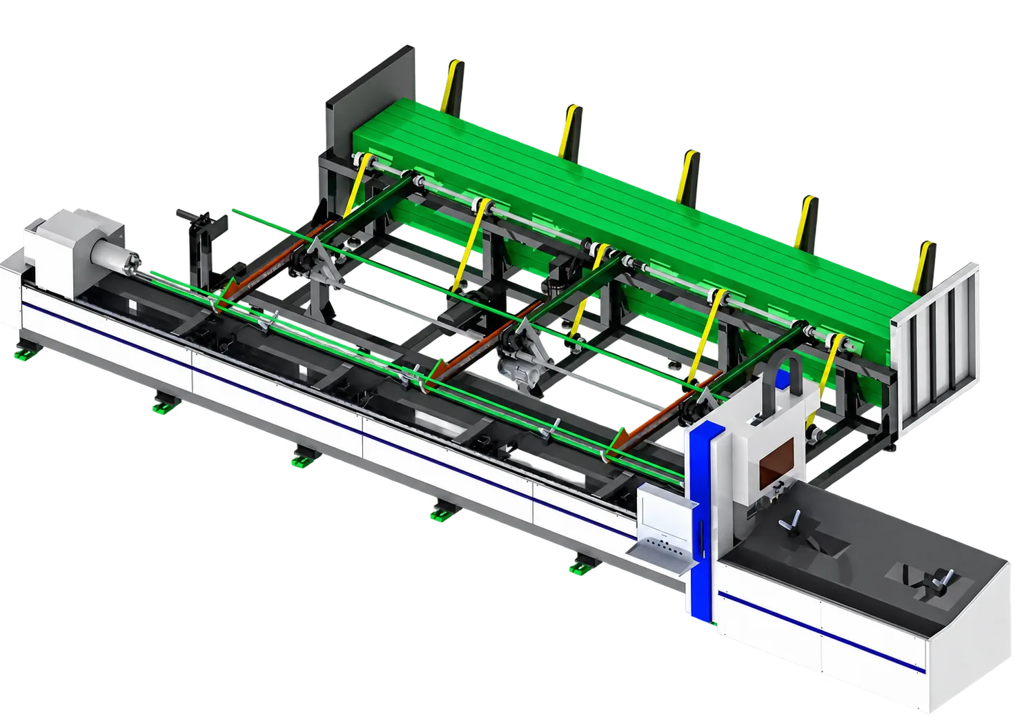
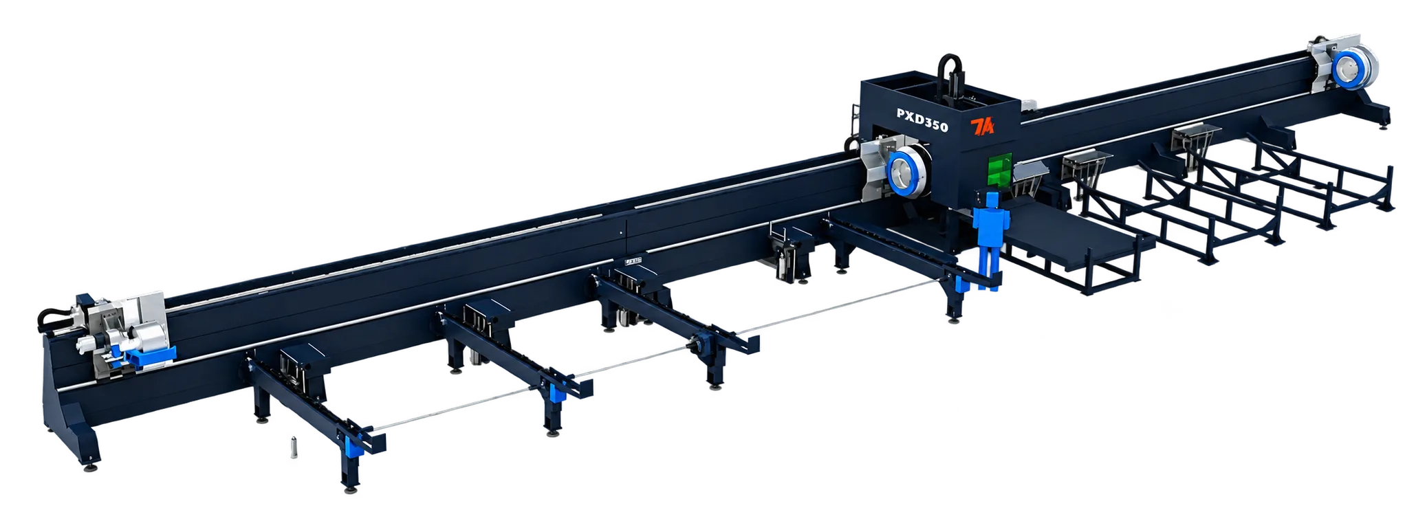
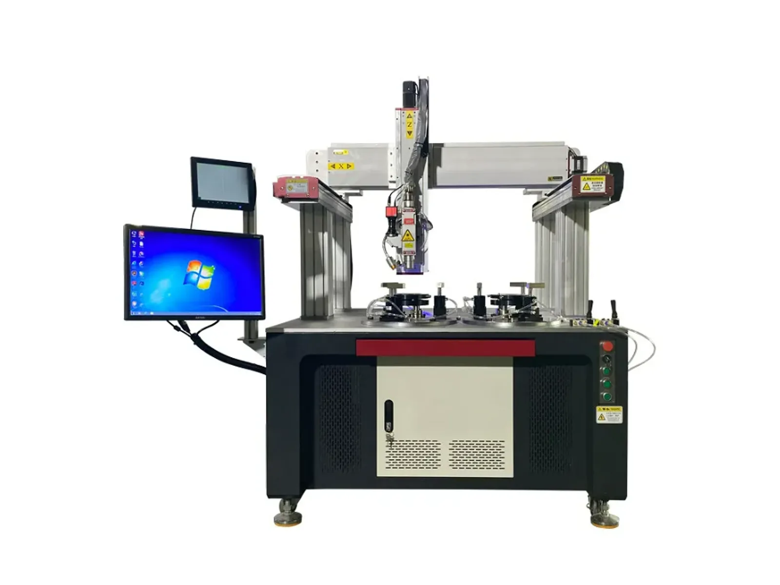
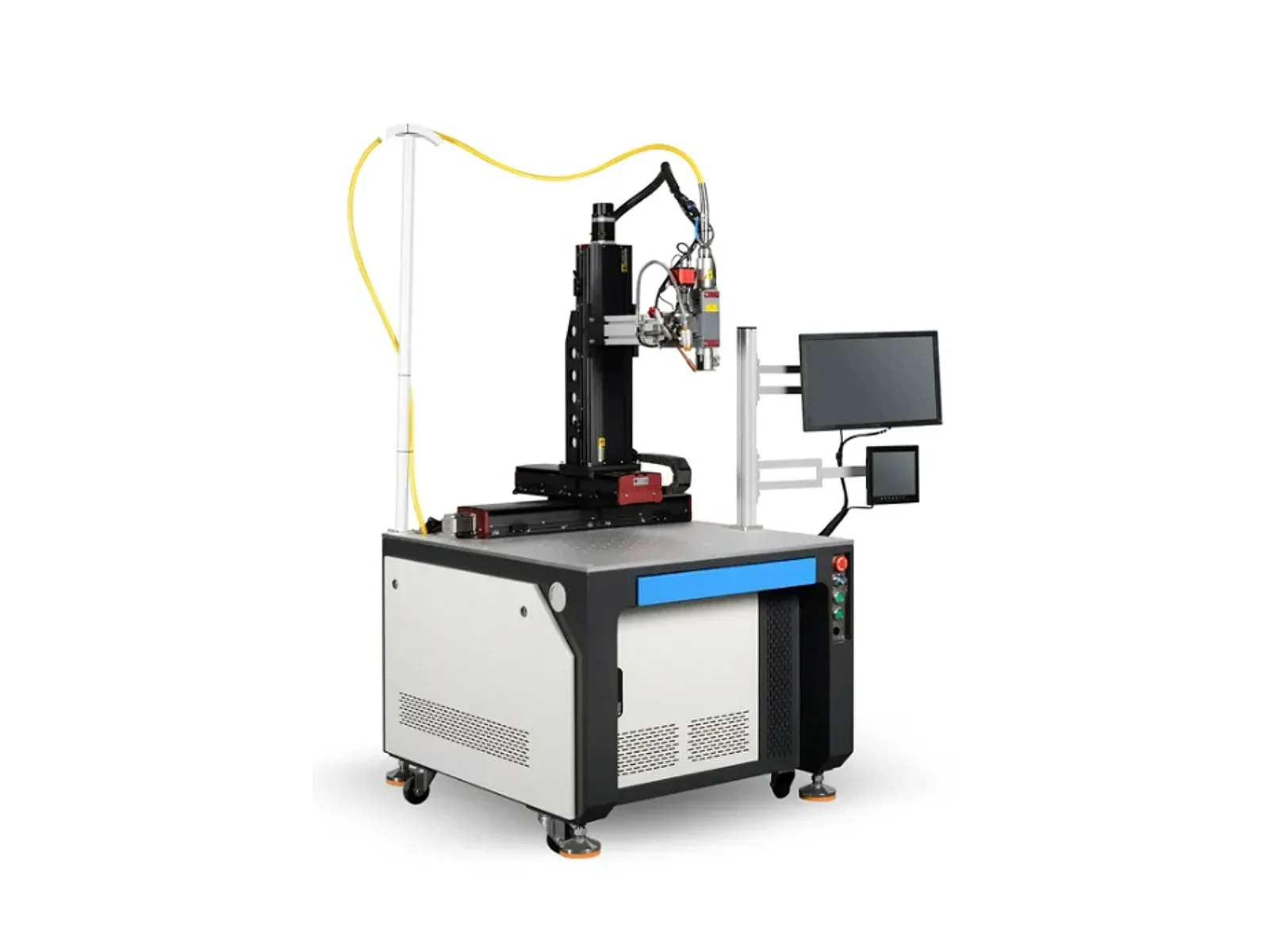
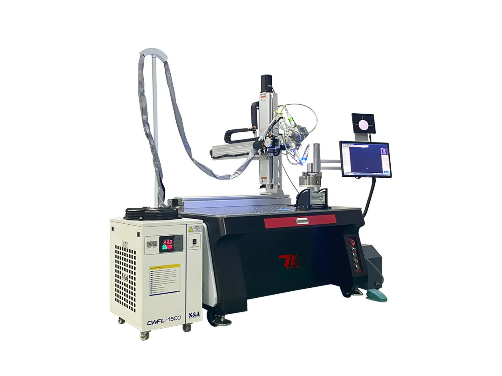
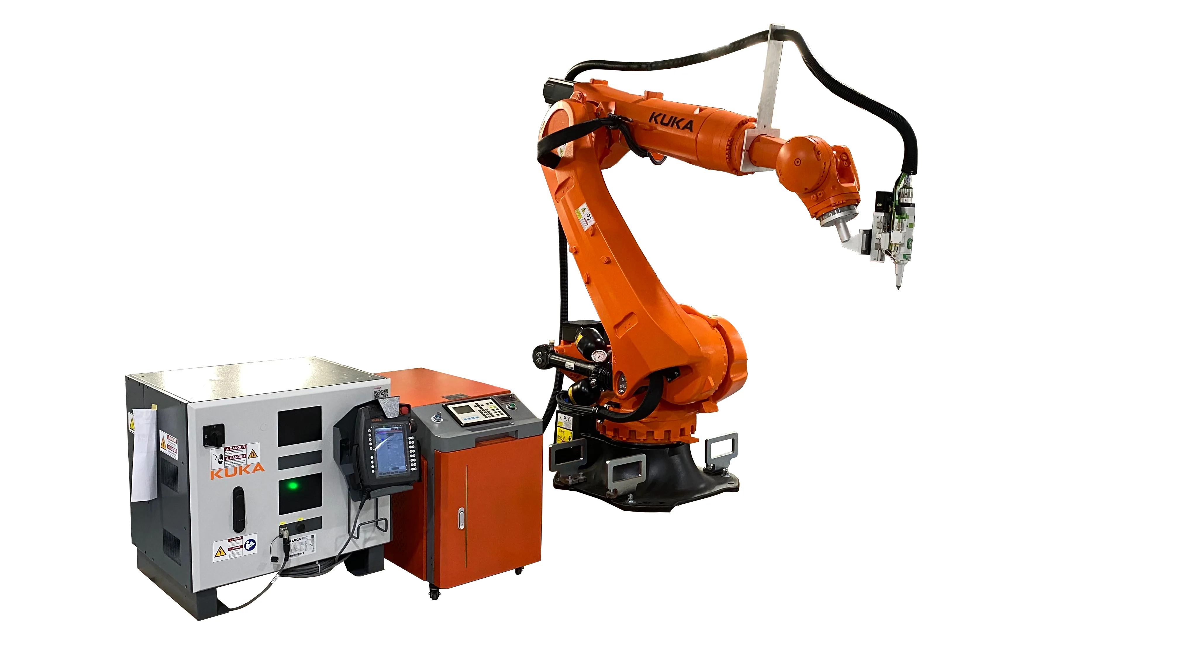
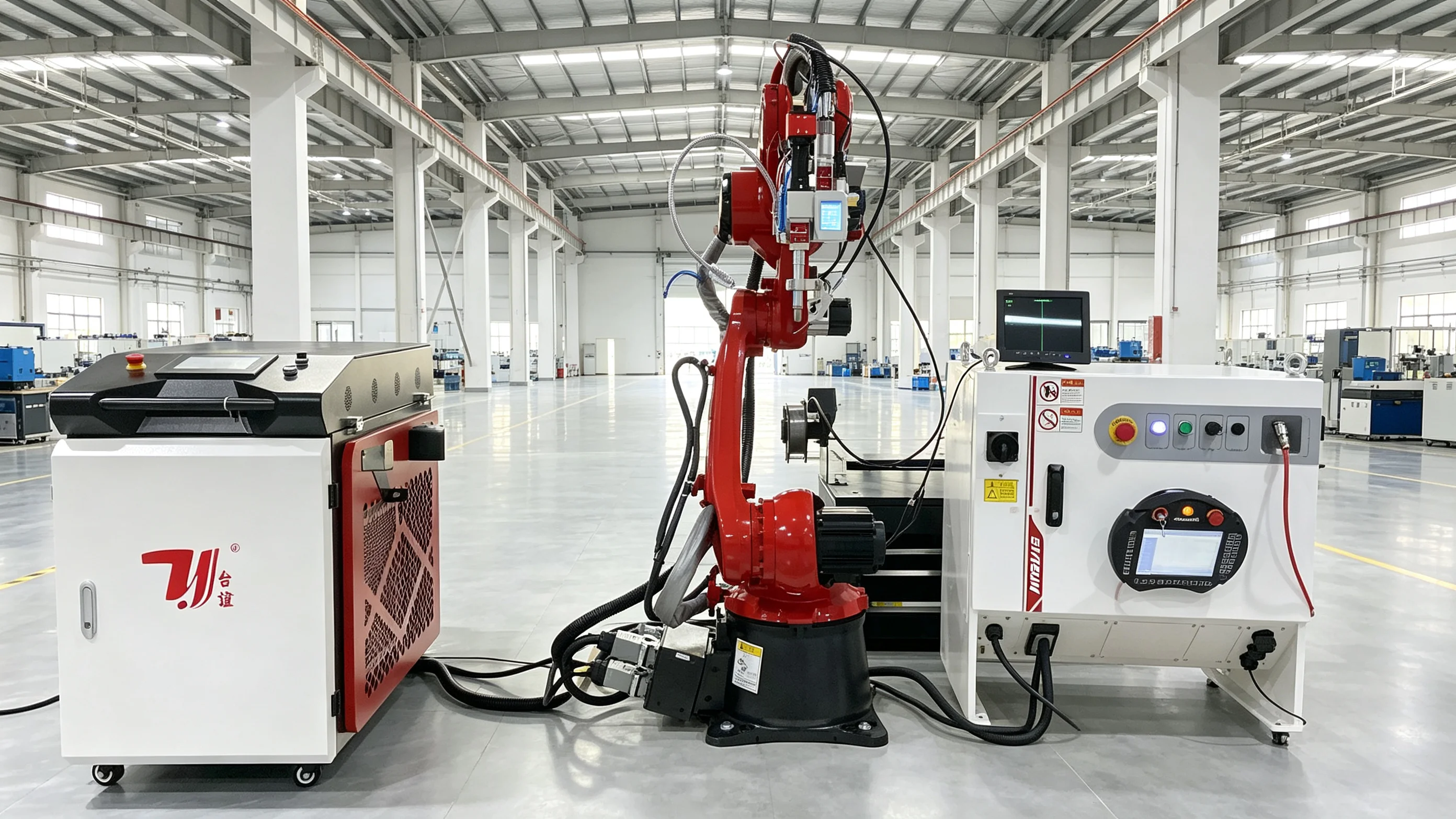
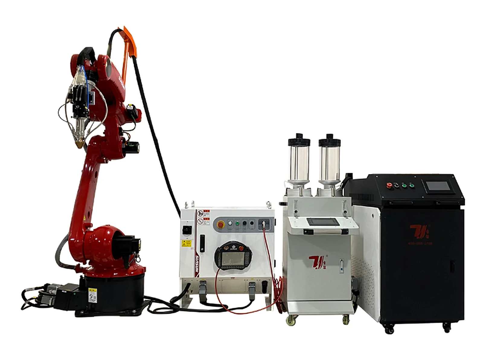
Robot cladding configuration
Robot Laser Cladding Machine
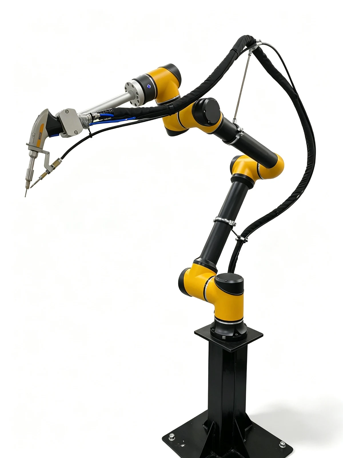
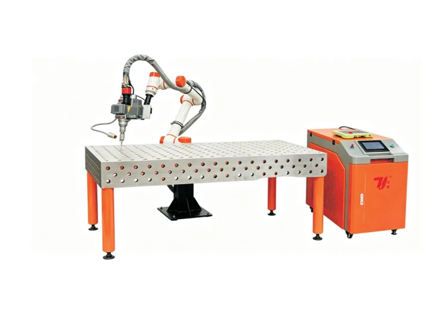
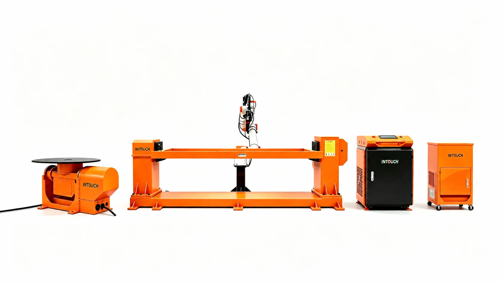
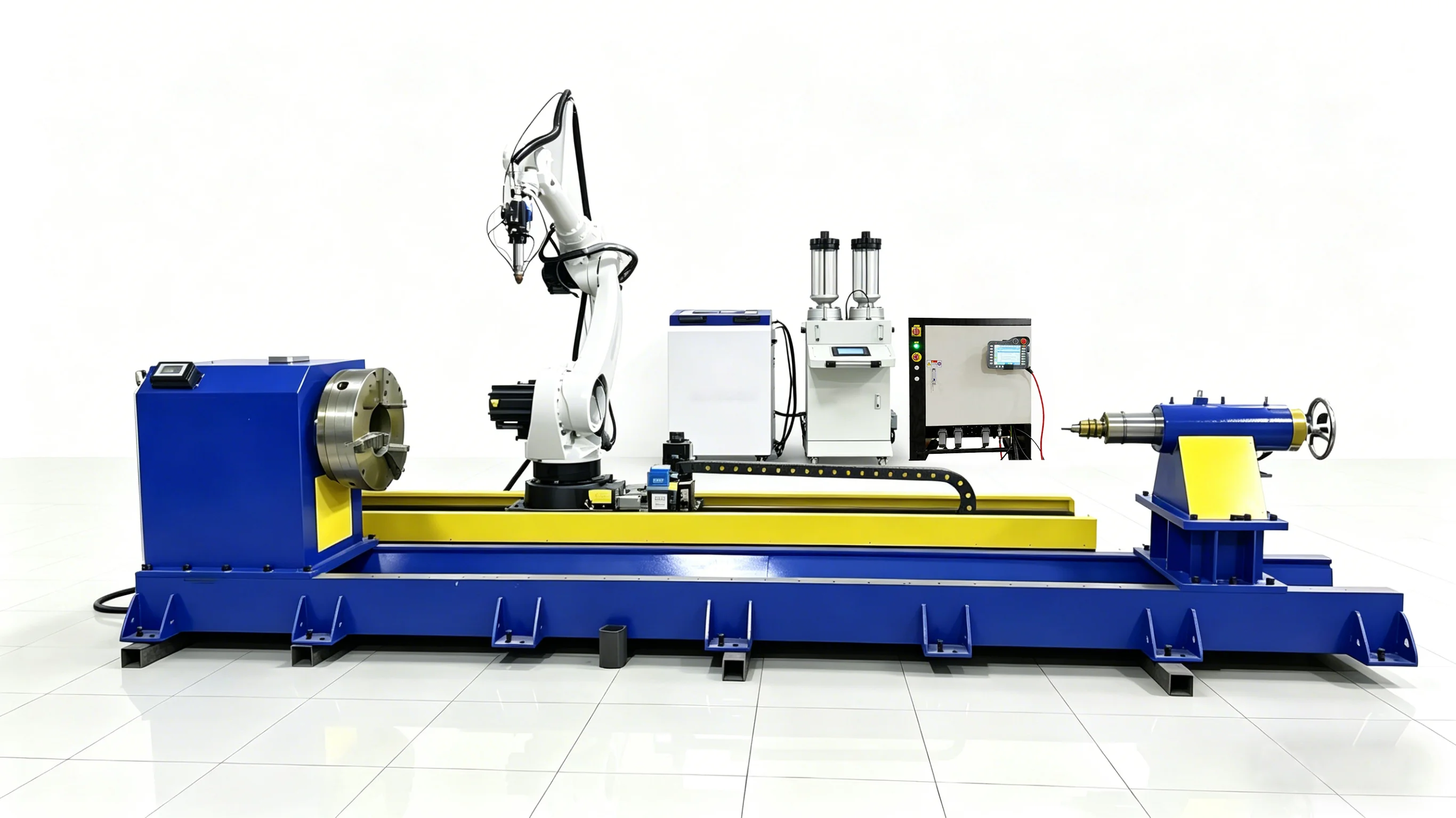
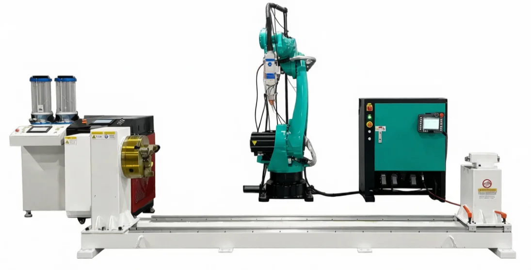
This TY-RF5018 robot laser cladding configuration follows programmed deposition paths on shafts, rollers, moulds and curved or irregular parts. Six-axis motion is combined with workholding selected to present the treatment surface to the cladding head.
Whole-machine warranty: 2 years · Final price and delivery timing depend on part geometry and material, target layer, laser power, robot reach, cladding head, powder feeder, workholding, guarding, extraction and installation scope.
Specifications
TY-RF5018 robot cladding configuration data
TY-RF5018 robot system
- Series
- TY-RF5018
- Robot structure
- 6-axis industrial robot
- Listed laser power
- 3,000 / 6,000 / 12,000 W
- Listed robot options
- Domestic / FANUC / KUKA / Yaskawa or configured equivalent
- Listed arm reach
- 1,800 / 2,000 mm, with other reaches configurable
- Positioning accuracy
- ±0.05 mm / ±0.002 in
Cladding process package
- Fiber-core diameter
- 600 μm
- Fiber length
- 20 m standard listing; customizable
- Fiber interface
- QBH
- Listed cladding spot
- Round 4 mm or square 10 / 20 mm
- Listed cladding thickness
- 0.5-2 mm / 0.020-0.079 in
- Process head
- Cladding head or hardening head, by configuration
Powder feeding and utilities
- Powder feeder
- Single or dual feeder, by configuration
- Powder-particle range
- 20-200 μm
- Listed powder-feeding accuracy
- ≤±2%
- Shielding gas
- Argon / nitrogen
- Power supply
- 380 V, 50/60 Hz
- Cooling / warranty
- Water cooling / 2-year whole-machine warranty
Configure six-axis cladding paths around the part
Six-axis path control
The robot follows programmed cladding paths around flat, axial, curved and special-shape surfaces while maintaining the selected head orientation.
Configurable process package
Laser power, cladding or hardening head, focal arrangement and listed spot options are selected against the material, geometry and target layer.
Workholding around the part
A positioner, rotary fixture, rail or other support can be configured when the component must rotate, translate or be presented at a controlled angle.
Integrated powder feeding
Single- or dual-feeder configurations supply the selected alloy powder while the laser, head, cooling and controls operate as one cell.
Robot and reach options
The listed configuration supports multiple robot brands and reach selections so the motion envelope can be matched to the workpiece and fixture.
Project review before build
Part drawings, material, surface condition, target layer, cycle expectations, guarding and installation requirements are reviewed before the final scope is fixed.
From part review to sample acceptance
The final cell is defined from the submitted component, access conditions, target cladding layer and production requirements.
- 01
Part drawing and cladding-area review
- 02
Base-material and surface-condition check
- 03
Target layer and cladding-material definition
- 04
Laser power and process-head selection
- 05
Robot reach and path-access verification
- 06
Positioner, rail and workholding design
- 07
Process trial and sample acceptance
- 08
Guarding, utilities and installation confirmation
External and complex surfaces for repair and strengthening
Part geometry alone does not determine feasibility. Surface condition, robot access, workholding, shielding, extraction and the target layer are reviewed together.
Other laser cladding configurations
TY-RF5018
Review the wider TY-RF5018 series and its robot, workholding and process-package options.
Internal-wall claddingTY-RF5018
A dedicated configuration for accessible internal surfaces of pipes, cylinders and sleeves.
Platform automatic claddingTY-RF2018
Open-platform automatic cladding for shafts, rollers and smaller repair parts.
Related industry solutions
Explore the applications and laser processes connected to this equipment.
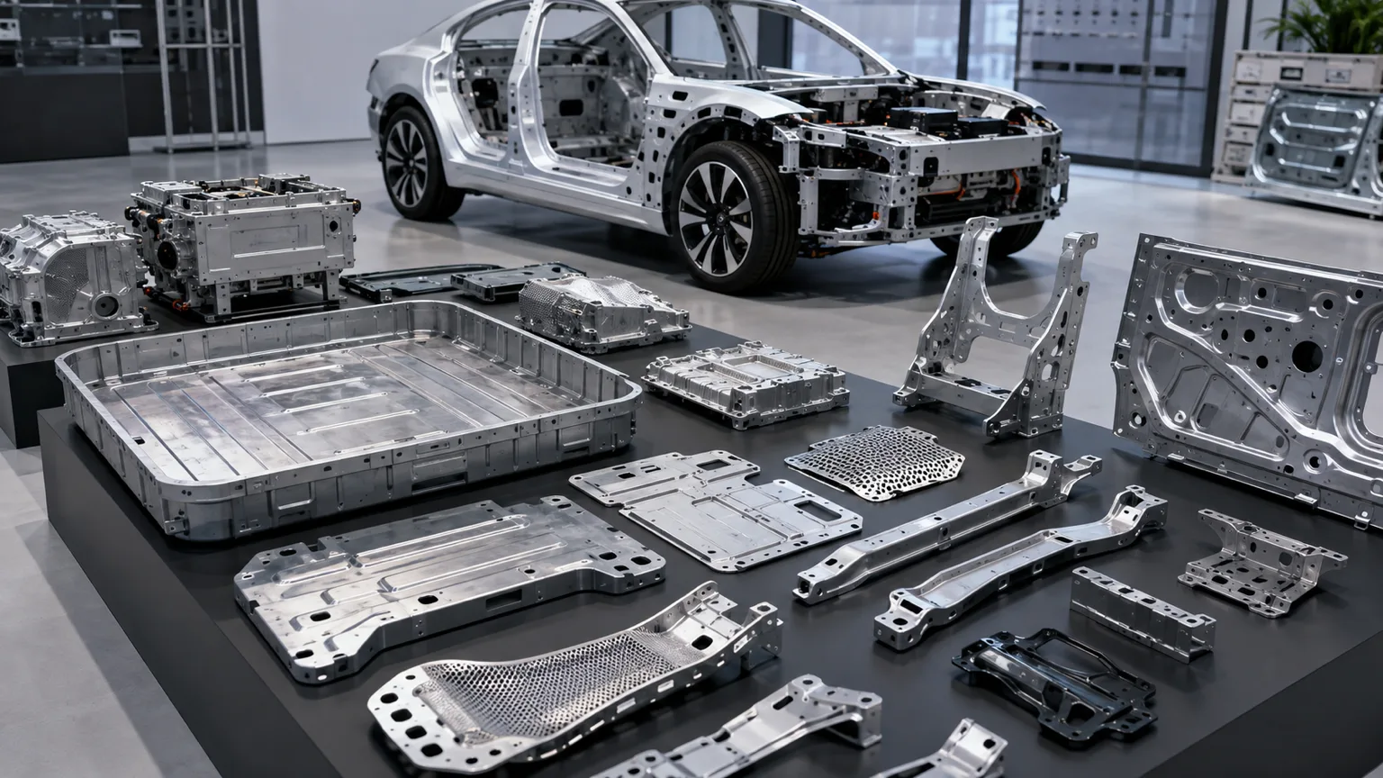
Automotive components
Laser processing for body structures, powertrain parts and battery components.
View solution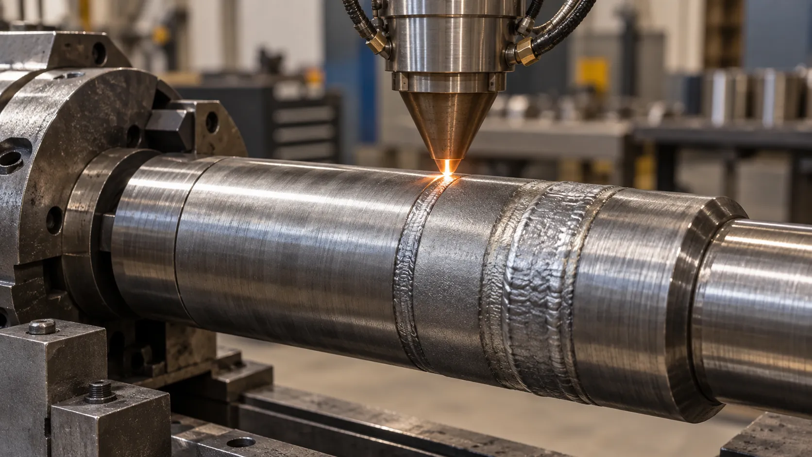
Laser cladding & repair
Restore worn surfaces on shafts, bores, screws and large components.
View solutionReview the robot path together with the fixture
Check the complete treatment path
Mark every cladding region on the part model, including edges, curves and surfaces near obstructions. Reach must be assessed with the head orientation and fixture in place; a nominal arm length alone does not confirm access to the whole surface.
Choose how the part moves
A positioner, rotary fixture, rail or support can be configured when the component needs rotation or translation. Describe the part dimensions and mass, loading method and locating surfaces so the motion package can be reviewed as one cell.
Specify the layer and acceptance plan
The base material, existing surface condition and target layer guide the process package. Agree the repair dimensions and inspection criteria before fixing the production target; robot positioning accuracy is not a guarantee of final part geometry or layer performance.
Machine selection questions
Which parts are listed for robot laser cladding?
The configuration covers reviewed shafts, rollers, moulds, hydraulic or mining components, and curved or irregular repair surfaces. Actual suitability depends on access, material, surface condition and the target layer.
Is a six-axis robot enough to reach every face of the part?
Not necessarily. Head orientation, fixtures and obstructions can limit access. The project may require a positioner, rail, different reach or a revised setup to present the treatment areas.
Is the rotary positioner included as standard?
Workholding and motion additions are selected by configuration. Identify the required positioner, fixture, supports or rail explicitly in the equipment proposal.
Can this external cladding configuration repair an internal bore?
Internal surfaces require a dedicated internal-wall head and bore-access review. Compare the internal-wall configuration rather than assuming an external cladding head can reach the same area.
What is needed to quote a robot cladding cell?
Send the part model, material, mass, surface condition, marked cladding areas, target layer and output requirement. Include loading arrangements and any constraints on robot space, fixtures or inspection.
Request a quote
Tell us the part. We will tell you the machine.
Price depends on part geometry and material, current condition, target layer, laser power, robot brand and reach, cladding head, powder feeder, positioner or rail, guarding, extraction and installation scope.
- Phone+86 153 6281 4831
- Emailsales02@taiyilaser.com
- WhatsApp+86 153 6281 4831