
Fixture-guided intersecting seams
Tee Pipe Laser Welding Machine
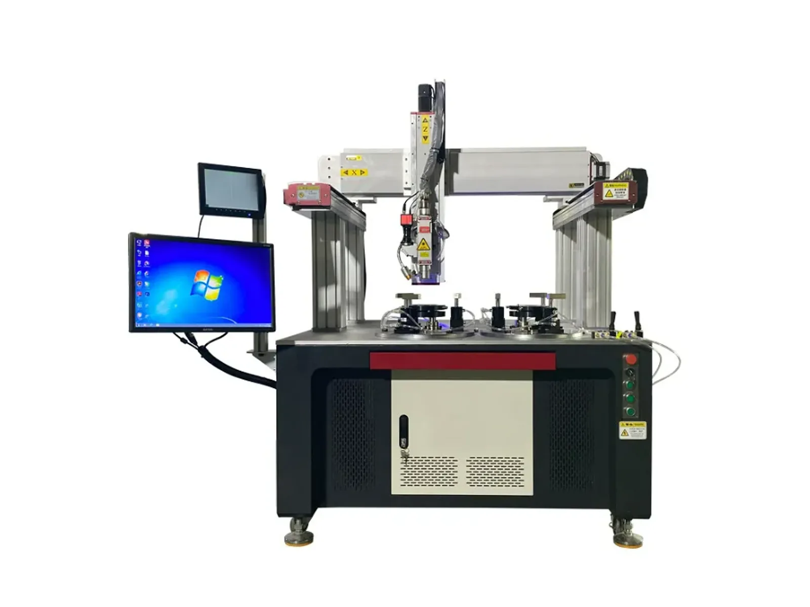
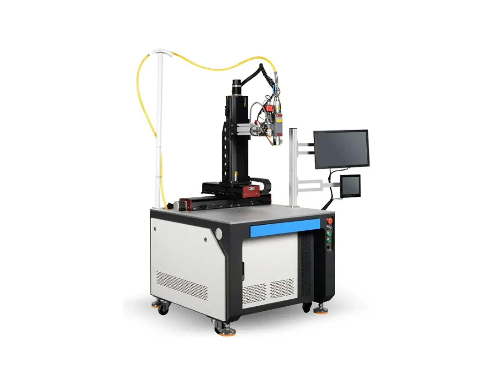
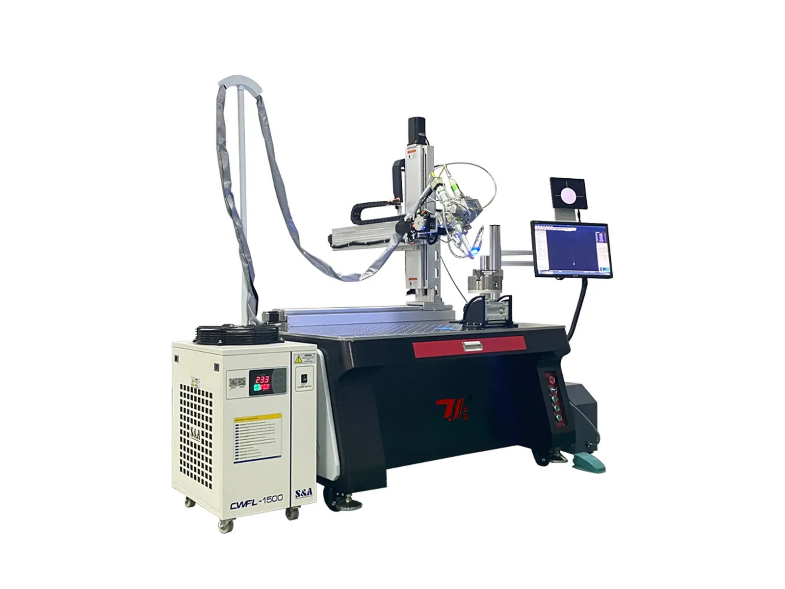
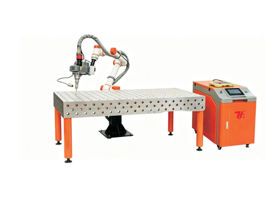
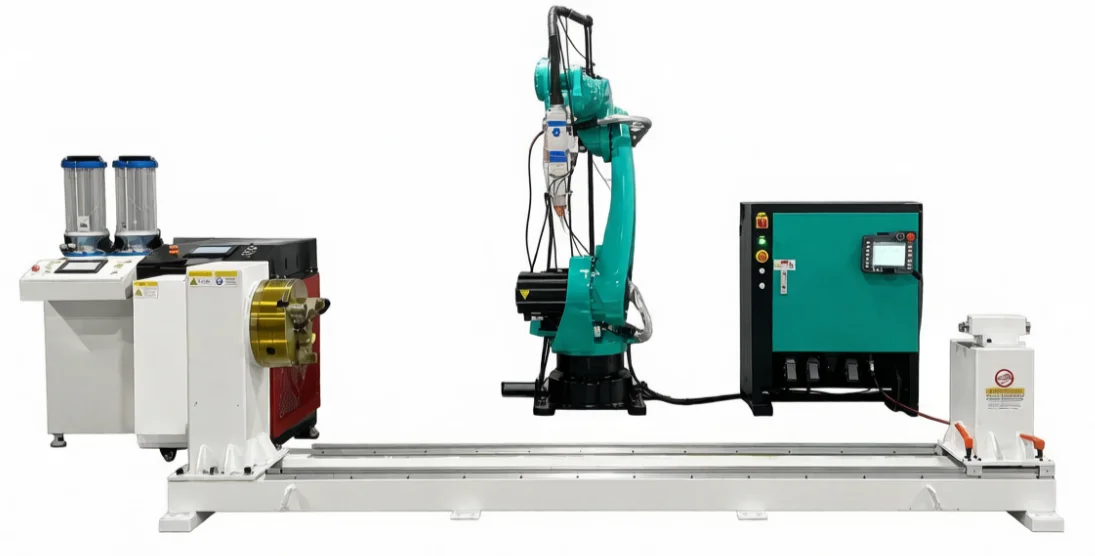
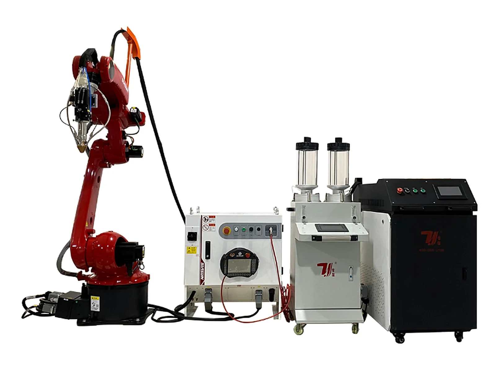
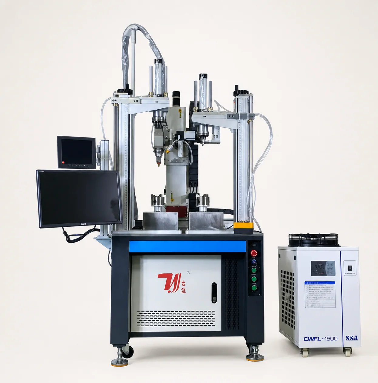
This dual-station laser welding cell is designed around intersecting joints in faucet bodies, stainless-steel tee fittings and related pipe parts. Branch geometry and weld-head access guide the custom fixture and station sequence.
Specifications
Document-listed configuration options
Laser and positioning · select by project
- Configuration status
- Document-listed options; confirm the compatible set for the submitted part
- Laser power
- 1,500 / 2,000 / 3,000 / 6,000 W (select one)
- Repeat positioning precision
- ±0.01 mm (manual listing)
- Station layout
- Dual-station standard presentation; multi-station layout available after review
- Operating guidance
- Operating system with CCD shown in the supplied manual
Optics and process · confirm as one set
- Laser wavelength
- 1,070 nm (manual listing)
- Pulse frequency
- ≤100 Hz (manual listing; confirm against the selected source)
- Pulse width
- 0.5-15 ms (manual listing; confirm against the selected source)
- Spot adjustment range
- 0.1-3 mm (manual listing)
- Laser-source options
- Raycus / IPG / JPT / MAX (project selection)
- Welding-head option
- Raytools HZG (project selection)
Workholding and utilities · confirm per cell
- Primary workpieces
- Faucet bodies, tee fittings and intersecting pipe joints
- Fixture package
- Custom fixture designed around the submitted workpiece and seam
- Cooling system
- Water cooling
- Electrical listing
- 220 / 380 V · 3-phase · 50 / 60 Hz (confirm for the selected supply)
- Cell envelope
- Manual diagram shows approximately 1,300 × 1,100 × 1,900 mm; confirm before layout approval
Build the fixture around the branch joint
This is an application-configured welding cell rather than a universal tee-fitting machine. Part location, clamp access, weld order and station count are fixed after the submitted workpiece is reviewed.
Dual-station workholding
Two fixture positions support repeat loading and welding workflows for faucet or tee-pipe parts. The actual operating sequence is confirmed with the target cycle.
Custom fixture development
Fixture contact points, clamping direction and weld access are designed from the submitted part drawing or sample rather than treated as a universal holder.
CCD-assisted operation
The supplied manual shows an operating system with CCD support for alignment and observation. Final vision scope depends on the seam and inspection requirement.
Power and optics selected together
The listed laser source, welding head, spot range and electrical supply are reviewed as one compatible project configuration before quotation.
From joint review to delivery
- 01
Machine-bed welding
- 02
Beam preparation
- 03
Heat treatment
- 04
Precision machining
- 05
Pre-assembly inspection
- 06
Machine assembly
- 07
Testing, debugging and acceptance
- 08
Delivery
Application scope for tee-pipe and faucet-body welding
Suitability depends on material, wall thickness, branch geometry, fit-up, surface-finish target and weld access. Submit the real part or drawing before the fixture and process route are fixed.
Compare the next automatic welding path
Five-axis automatic welding
Compare five-axis linkage when the submitted seam requires three-dimensional access.
Sanitaryware fixture systemSink clamp laser welding
Dedicated workholding for stainless-steel sink clamps, buckles and accessories.
Application systemsAutomatic welding range
Compare gantry, multi-axis and workpiece-specific automatic welding systems.
Related industry solutions
Explore the applications and laser processes connected to this equipment.
View all industry solutions
Review the intersecting seam from every approach
Show the branch and main body together
Provide the branch angle, outside diameters, wall thicknesses and seam location on the assembled part. The fixture must locate both components while leaving access around the intersection; separate component dimensions do not fully describe that task.
Define the locating and viewing method
Custom fixtures establish part location, while the supplied system includes CCD support for alignment and observation. The camera view and its role should be reviewed against the actual joint rather than assumed to find every seam automatically.
Set the work sequence and acceptance criteria
Define loading, clamping, welding order and unloading for the two fixture positions. Include the required seam finish and any leakage inspection method in the project brief; machine repeat positioning is not a finished-joint acceptance result.
Machine selection questions
Does this machine weld longitudinal seams to manufacture tubes?
This page covers intersecting branch joints in faucet bodies, tee fittings and related assemblies. Longitudinal tube-manufacturing seams are a different application and are not established by this cell description.
Can it weld different tee or cross-pipe sizes?
Variant sizes and cross-pipe joints can be reviewed using part-specific or changeable fixtures. Branch orientation, clamping access and the complete seam path determine the configuration.
What does CCD support do on this cell?
The supplied manual shows CCD-assisted alignment and observation. The final viewing and positioning scope is confirmed with the part; this does not establish automatic seam finding for every geometry.
Are the two stations guaranteed to weld simultaneously?
The presented cell has two fixture positions, but the operating sequence is project-specific. Confirm how loading and welding are arranged; station count alone does not establish simultaneous welding or a fixed output.
What should I send for a tee-pipe welding quote?
Send the assembly drawing or sample, branch angles and diameters, material and wall thickness, seam position, variant list, cycle target and inspection requirements. Include any constraints on loading and the surrounding production layout.
Request a quote
Tell us the part. We will tell you the machine.
Configuration and quotation are prepared after the workpiece, material, joint drawing, fixture requirement and target cycle are reviewed.
- Phone+86 153 6281 4831
- Emailsales02@taiyilaser.com
- WhatsApp+86 153 6281 4831